6
1.2 LED Display
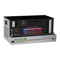
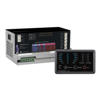
Figure 3 PMSWLED-2 switch panel
Table 1 Front panel of PMSWLED-2
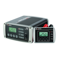
Table 2 LED indication of PM235
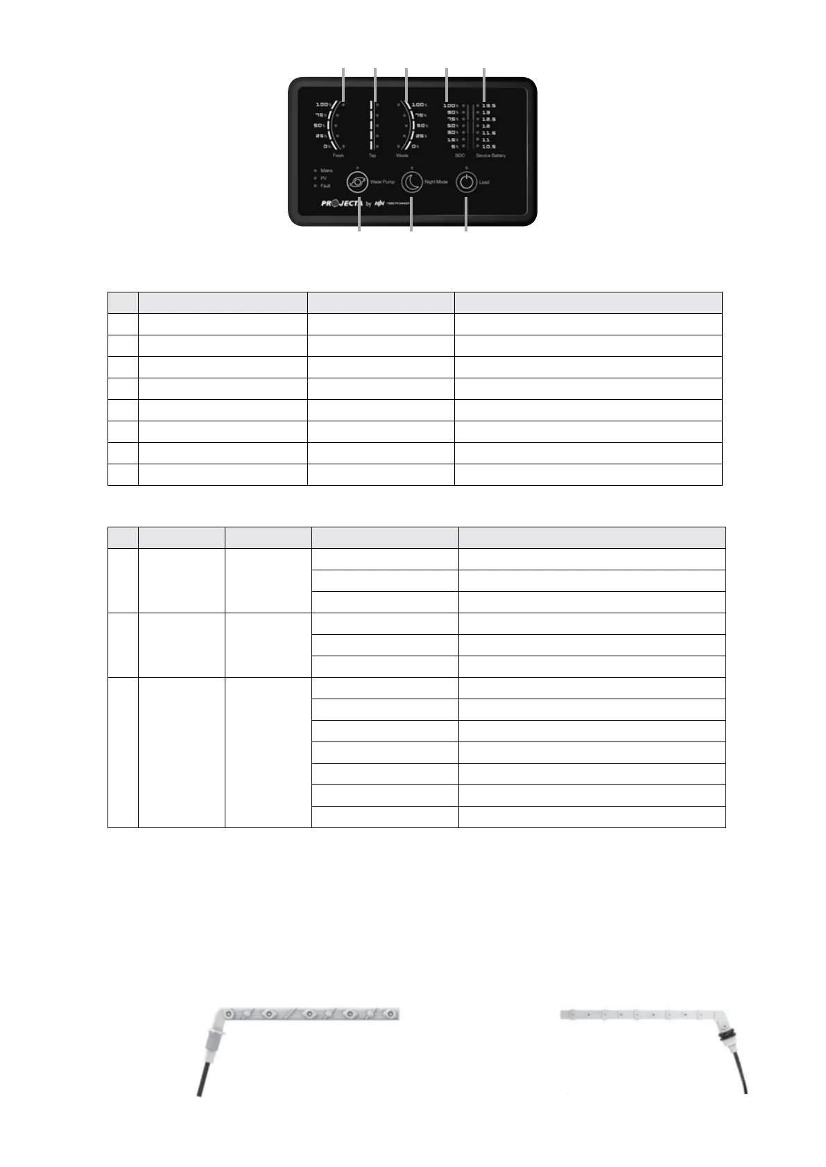
1.3 Water Tank Probes
A maximum of up to 3 probes can be monitored by the system.
NOTE: Always check the probe required for the water tank before purchase. If the probe included does not t the water tank,
please contact the seller.
There are 2 probe styles:
PMWS200:
• Side installation
• Suitable for water tank
• Depth >200mm
Figure 5 PMWS400Figure 4 PMWS200
PMWS400:
• Side installation
• Suitable for water tank
• Depth 300-400mm
1
4
2
5 6 7 8
3
N
O
LABEL DEFINITION DESCRIPTION
1 Water Pump DC load control Load control, on/off control
2 Night Mode Scene mode Refer to 2.10
3 Load DC load control Load control, on/off control. Refer to 2.7
4 Fresh Water Tank Sensor Detect the level of fresh water tank
5 Tap Water Tank Sensor Detect the level of tap water tank
6 Waste Water Tank Sensor Detect the level of waste water tank
7 Service Battery SOC Detect the state of the charge of service battery
8 Service Battery Voltage Detect the voltage of service battery
N
O
LABEL COLOUR STATUS DESCRIPTION
1 Main Green
ON Battery charged or power supply mode
Flash Battery charging under grid electricity
OFF NO AC input
2 PV Green
Solid Battery charged
Flash Battery charging under solar energy
OFF NO solar input / AC charging / Aux charging
3 Fault Red
ON Short circuit
1 Flash Service battery voltage low
2 Flash Service battery voltage high
3 Flash Over temp (heat sink)
4 Flash Bulk charge timeout
5 Flash VCR anomaly
6 Flash Over temp (environment)
 Loading...