CROMOBEAM250
12
3.6 LINKING
Several units may be interconnected in order to control all further slave units to the same eect of the
master unit.
1. Connect the DMX OUT of the master unit via 3-pole XLR cable to the DMX IN of the rst slave unit.
2. Connect the DMX OUT of the rst slave unit to the DMX IN of the second slave unit, etc. until all units are
connected in a chain.
3.7 DMX CONFIGURATIONS
CROMOBEAM250 is equipped with 2 DMX conguration.
• Press the MENU button and select, via the directional buttons, the [Intro] menu choice, then press the
ENTER button to conrm the choice.
• Press the UP and DOWN buttons to select [Channels] menu voice and conrm the choice by pressing the
ENTER button.
• Select a DMX conguration: [Basic] or [Adavnced], and press ENTER button.
The tables on page 12 indicate the operating mode and DMX value. The CROMOBEAM250 is equipped with
3-pole XLR connections.
3.8 DMX MODE
• Press the MENU button and select, via the directional buttons, the [Intro] menu choice, then press the
ENTER button to conrm the choice.
• Press the UP and DOWN buttons to select [Channels] menu voice and conrm the choice by pressing the
ENTER button.
• Select [DMX512], and press ENTER button.
3.9 CONNECTION OF THE DMX LINE
DMX connection employs standard XLR connectors. Use shielded pair-twisted cables with 120Ω impedance
and low capacity.
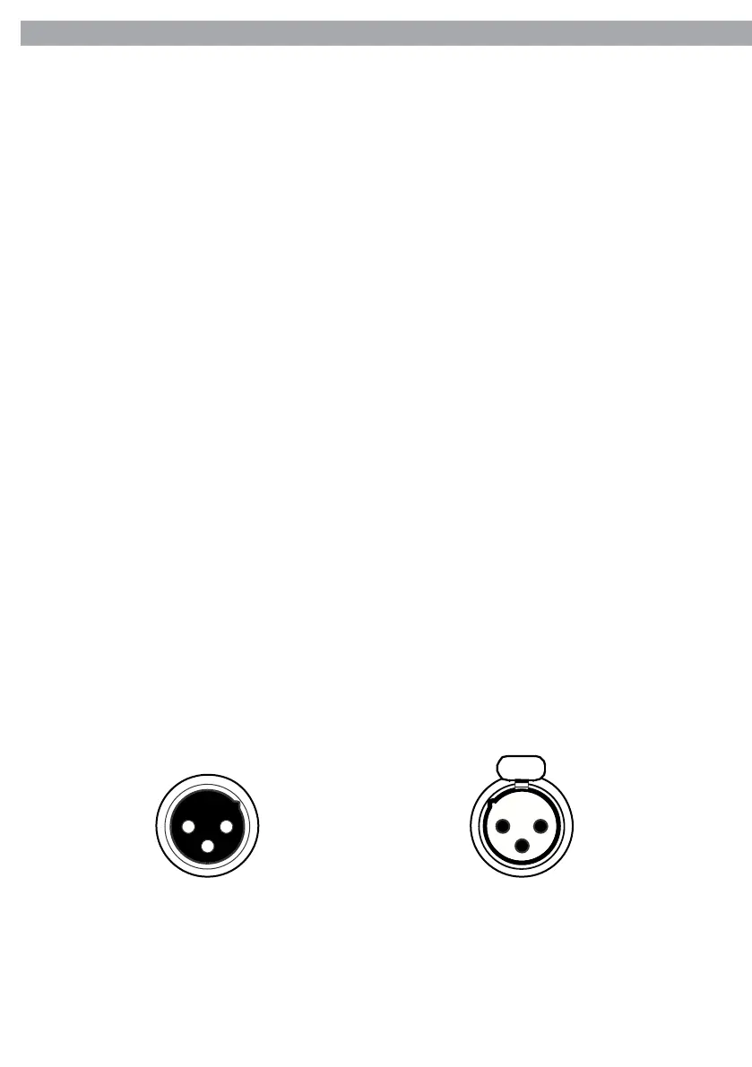
The following diagram shows the connection mode:
1
3
21 2
3
Pin1 : GND - Shield
Pin2 : - Negative
Pin3 : + Positive
DMX - INPUT
XLR plug
DMX - OUTPUT
XLR socket
ATTENTION
The screened parts of the cable (sleeve) must never be connected to the system’s earth, as this would cause
faulty xture and controller operation.
Over long runs can be necessary to insert a DMX level matching amplier.
For those connections the use of balanced microphone cable is not recommended because it cannot trans-
mit control DMX data reliably.