13
CROMOBEAM250
Number of
DMX channels
Start address
(example)
Used DMX
addresses
Next possible start
address for unit No.1
Next possible start
address for unit No.2
Next possible start
address for unit No.3
8 33 33-40 41 49 57
11 33 33-43 44 55 66
3.11 ADJUSTING THE START ADDRESS
To able to operate the CROMOBEAM250 with a light controller, adjust the DMX start address for the rst a
DMX channel. If e. g. address 33 on the controller is provided for controlling the function of the rst DMX
channel, adjust the start address 33 on the CROMOBEAM250. The other functions of the light eect panel
are then automatically assigned to the following addresses.
An example with the start address 33 is shown below:
• Press the MENU button and select, via the directional buttons, the [Intro] menu choice, then press the
ENTER button to conrm the choice.
• Press the UP and DOWN buttons to select [Address] menu voice and conrm the choice by pressing the
ENTER button.
• Edit the DMX address value into the [1 - 512] range using the UP and DOWN buttons.
• Connect the controller DMX input to the DMX output of the rst unit.
• Connect the DMX output to the DMX input of the following unit. Connect again the output to the input
of the following unit until all the units are connected in chain.
• When the signal cable has to run longer distance is recommended to insert a DMX termination on the
last unit.
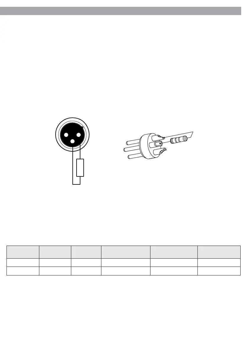
3.10 CONSTRUCTION OF THE DMX TERMINATION
The termination avoids the risk of DMX 512 signals being reected back along the cable when they reaches
the end of the line: under certain conditions and with certain cable lengths, this could cause them to cancel
the original signals.
The termination is prepared by soldering a 120Ω 1/4 W resistor between pins 2 and 3 of the 5-pin male XLR
connector.
Example:
3 pin XLR connector
1 2
3
120 Ω
2
3
1