Page 20
Please take note of the following safety information prior to installation:
WARNING!
Make sure that
• the maximum permissible water flow rate is not exceeded and
• the UV transmission does not drop below the minimum permissible levels
otherwise adequate treatment will no longer be guaranteed!
The maximum permissible water flow rate is defined in the supplied datasheet.
It is an integral function of the required radiation exposure level and of the minimum permissible
UV transmission of the water to be treated.
ATTENTION!
• The place of installation must be dry and frost-free while ensuring the UV system is
protected from the effects of chemicals, dyeing agents and vapours.
• The ambient temperature and the radiation temperature in the immediate vicinity must
not exceed 40 °C!
• If the water to be disinfected contains solid particles or turbidity substances, a suitable
filter should be installed upstream of the UV system.
• Make sure that the maximum permissible operating pressure is not exceeded.
IMPORTANT!
Despite the use of modern lamp ballasts with protective lamp ignition, the UV system
should be operated such as to avoid frequently switching the UV lamps on and off.
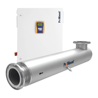
5.1 Radiation Chamber
The design and version of the radiation chamber are defined in the “Technical Data” (Section 8).
5.1.1 Installation
ATTENTION!
• Leave sufficient space for maintenance and servicing work!
The necessary clearance is defined in the dimensions sheet (changing lamp protective
tube).
Vertical wall mounting ➤ Using the installation material provided, secure the radiation chamber vertically on a wall or a
suitable frame. It must be possible to operate the manual wiper.
Reclined/horizontal ➤ Using the installation material provided, secure the radiation chamber horizontally on a wall or
a suitable frame.
CAUTION!
The outlet flange must face either vertically upward or vertically downward!
Otherwise, it will not be possible to fully vent the radiation chamber via the connections
provided!
5.1.2 Fitting Knob
The knob is supplied separately with some types of system. The knob must be fitted now:
➤ Slacken off the clamping screw a little (approx. 1/4 turn in counterclockwise direction)
➤ Completely pull out the wiper rod
➤ Use a WAF 11 open-ended spanner to secure the knob (with fixing bush) onto the wiper rod
➤ Slide the wiper rod completely into the radiation chamber
➤ Lock the fixing bush in the clamping screw
➤ Lightly tighten the clamping screw by hand (approx. 1/4 turn in clockwise direction)
Assembly and Installation