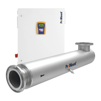
Page 22
Assembly and Installation
• Connect a PE conductor to the radiation chamber and to the chamber cover!
• Secure the power supply by means of a suitable residual current-operated circuit
breaker!
• Only an authorised electrician is permitted to open the control cabinet!
• The lamp connection cable and the sensor cable must not be extended!
• Electrical installation must be performed by an authorised electrician using the supplied
documentation and diagrams (circuit diagram).
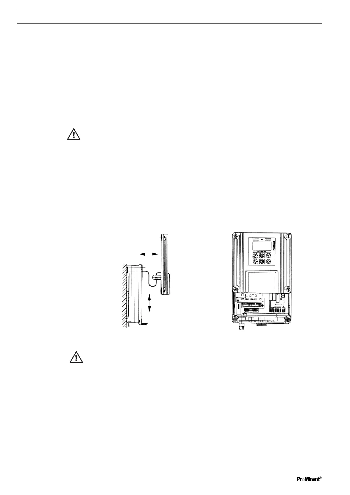
5.2.3 Opening Control Unit
IMPORTANT!
It is necessary to open the control unit only if it is not installed in the control cabinet.
WARNING!
Before opening, make sure that no voltage is applied to the control unit!
➤ Undo the 4 screws at the top of the housing
➤ Open the housing:
for this purpose exert pressure with the index finger on to the front edge of the housing while
simultaneously pulling forward so that the catch hook disengages
➤ Carefully pull the upper section forward away from the lower section (both sections are
connected by a ribbon cable!)
➤ Fit the upper section with both guide rails in the approx. 80 mm high plug-in slot
All connection terminals are now freely accessible. Blanked off holes that must be broken out to
insert the connection cables are provided on the underside of the control unit.
The openings in the rear row are intended for PG-11 screwed glands.
The 5 openings in the front row are intended for PG-7 screwed glands.
ATTENTION!
Use the appropriate tools to break out the blanked off cable leadthroughs on the underside
of the control unit so as no to damage the pc-board and the thread.
➤ Break out blanked-off cable leadthroughs on the underside of the control unit
➤ First install the cables in the rear row:
Fit screwed gland, thrust collar and seal from supplied supplementary kit on the cable, screw
into the threaded hole and tighten by hand
➤ Pull PG-7 screwed glands over the cable and lock with lock nut
➤ Route strands to the terminals corresponding to the terminal connection diagram
➤ Connect unused terminals to the corresponding plug connectors
➤ Close control unit
Fig. 3: Opening control unit