Tab. 1: Sigma
Size Motor flange Q
71 B 14/105 29
- 56C/138 1.14”
71 B 14/105 29
80 B 14/105 52.5
63 B 5/140 * (26)
Dimensions in mm - unless otherwise indicated.
* Motor is fitted directly onto the motor flange without intermediate flange
and claw coupling.
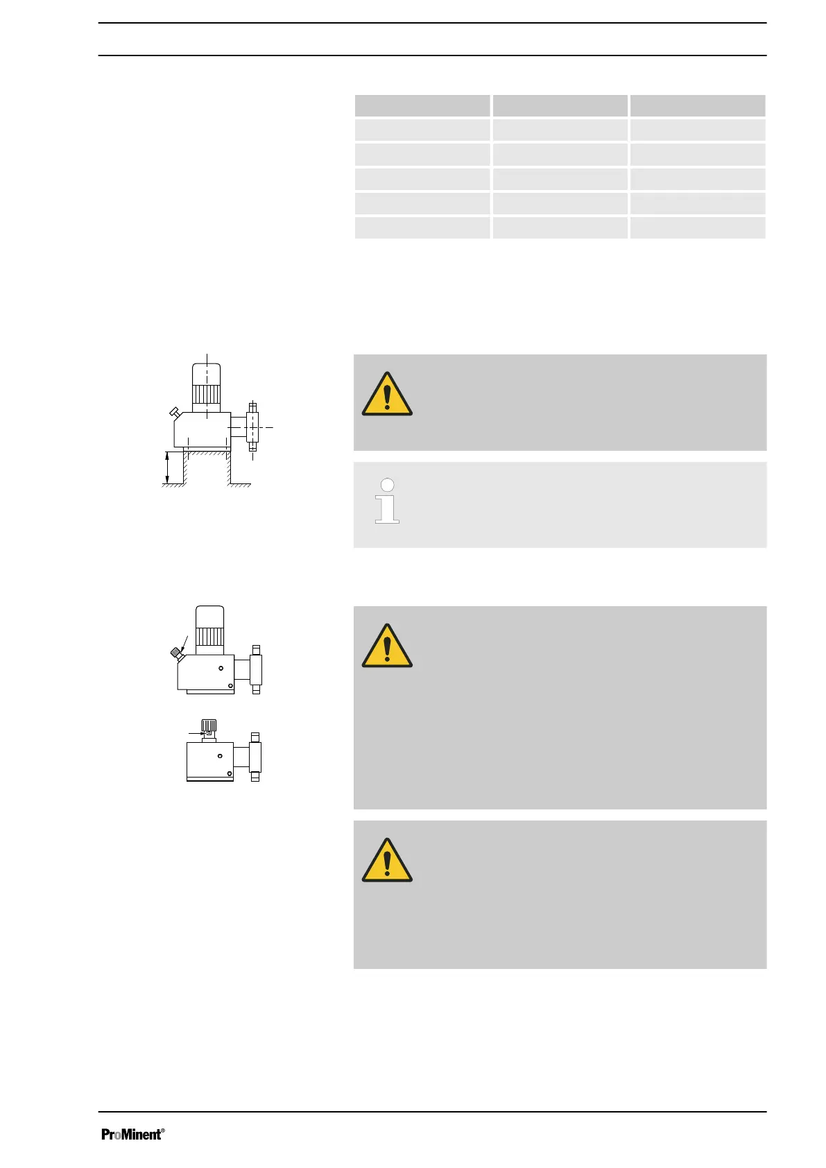
WARNING!
The pump can break through the base or slide off it
– Ensure that the base is horizontal, flat and perma‐
nently load-bearing.
Capacity too low
Vibrations can disturb the liquid end valves.
–
Do not allow the base to vibrate.
WARNING!
Motor may overheat
If the necessary cooling air supply is not guaranteed, the
motor may overheat. In an area at risk from explosion, it
could trigger an explosion.
– Maintain sufficient clearance between the air intake
opening and the walls. The distance should be
greater than 1/4 of the diameter of the air intake
opening.
–
The fan must not suck in the exhaust air from other
devices.
CAUTION!
Danger from incorrectly operated or inadequately main‐
tained pumps
Danger can arise from a poorly accessible pump due to
incorrect operation and poor maintenance.
– Ensure that the pump is accessible at all times.
–
Adhere to the maintenance intervals.
Position the pump so that control elements, such as the stroke length
adjustment knob or the indicating dial A, are easily accessible.
Base
Fig. 11
Space requirement
Fig. 12
Assembly
25