MVI56-MCM ♦ ControlLogix Platform Reference
Modbus Communication Module
Page 90 of 159 ProSoft Technology, Inc.
July 24, 2008
As shown in the illustration above, all data transferred between the module and
the processor over the backplane is through the input and output images. Ladder
logic must be written in the ControlLogix processor to interface the input and
output image data with data defined in the Controller Tags. All data used by the
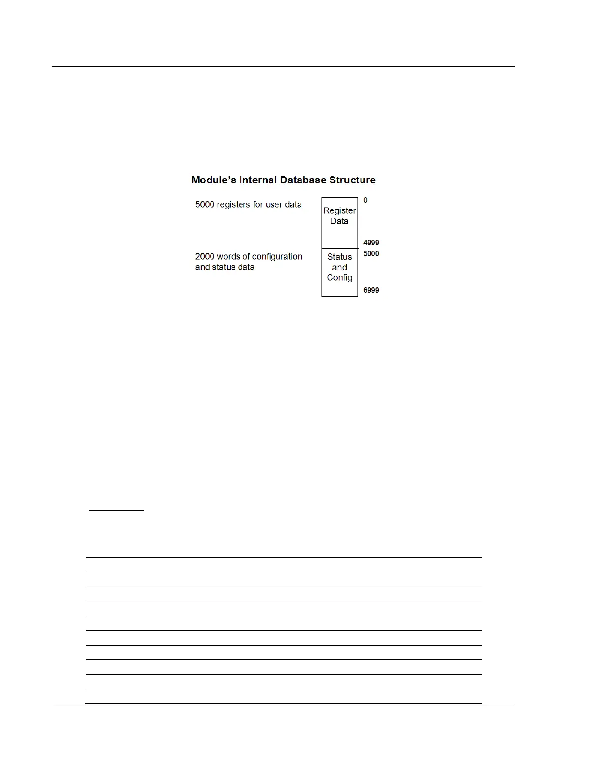
module is stored in its internal database. This database is defined as a virtual
Modbus data table with addresses from 0 (40001 Modbus) to 6999 (47000
Modbus). The following illustration shows the layout of the database:
Data contained in this database is paged through the input and output images by
coordination of the ControlLogix ladder logic and the MVI56-MCM module's
program. Up to 248 words of data can be transferred from the module to the
processor at a time. Up to 247 words of data can be transferred from the
processor to the module. Each image has a defined structure depending on the
data content and the function of the data transfer as defined below.
8.2.6 Normal Data Transfer
Normal data transfer includes the paging of the user data found in the module's
internal database in registers 0 to 4999 and the status data. These data are
transferred through read (input image) and write (output image) blocks. Refer to
Integrating the Sample Ladder Logic into an Existing Project (page 142) for a
description of the data objects used with the blocks and the ladder logic required.
The structure and function of each block is discussed below.
Read Block
These blocks of data transfer information from the module to the ControlLogix
processor. The structure of the input image used to transfer this data is shown in
the following table:
Offset Description Length
0 Reserved 1
1 Write Block ID 1
2 to 201 Read Data 200
202 Program Scan Counter 1
203 to 204 Product Code 2
205 to 206 Product Version 2
207 to 208 Operating System 2
209 to 210 Run Number 2
211 to 217 Port 1 Error Status 7