4.9.2 Alarm Code
Battery charger short circuit
Input L/N wiring reversed or PE
disconnect
4.10 UPS Parallel
4.10.1 Redundancy Introduction
N+X is currently the most reliable power supply structure. N represents the minimum UPS number that
the total load needs, X represents the redundant UPS number, i.e. the fault UPS number that the
system can handle simultaneously. When the X is larger, the reliability of the power system is higher.
For occasions where reliability is highly depended on, N+X is the optimal mode. As long as the UPS is
equipped with parallel cables, up to 3 units UPS (only for 6KVA or 10KVA) can be connected in parallel
to realize output power sharing and power redundancy.
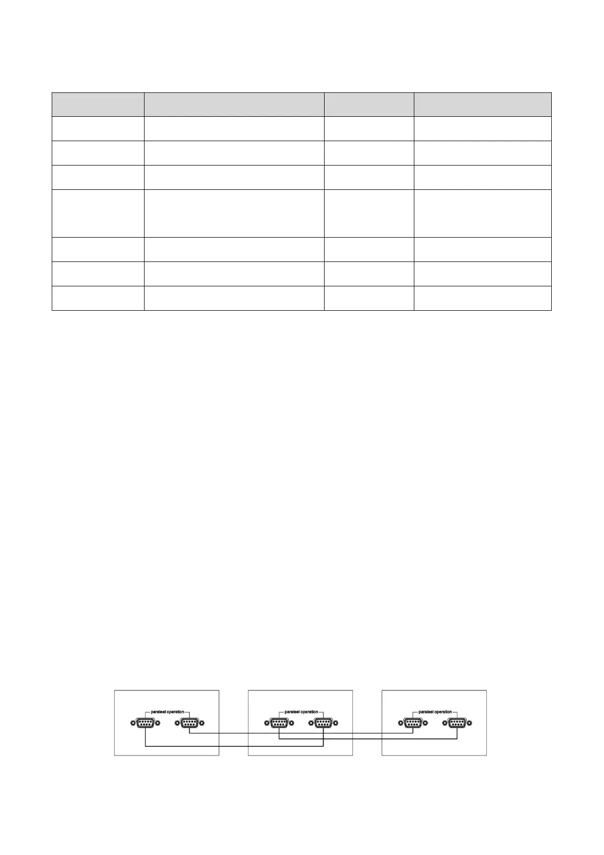
4.10.2 Parallel Installation
Parallel UPS is an optional function for user, before installing a new parallel UPS, users need to prepare
parallel accessories and ask service person to help for information. The number of parallel UPS is up to
3 units maximum. Each parallel UPS need an independent battery bank or battery pack.
4.10.2.1 Install the parallel card on UPS, connect each UPS one by one with parallel cable, the parallel
card is the communication port between UPS.