15
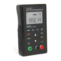
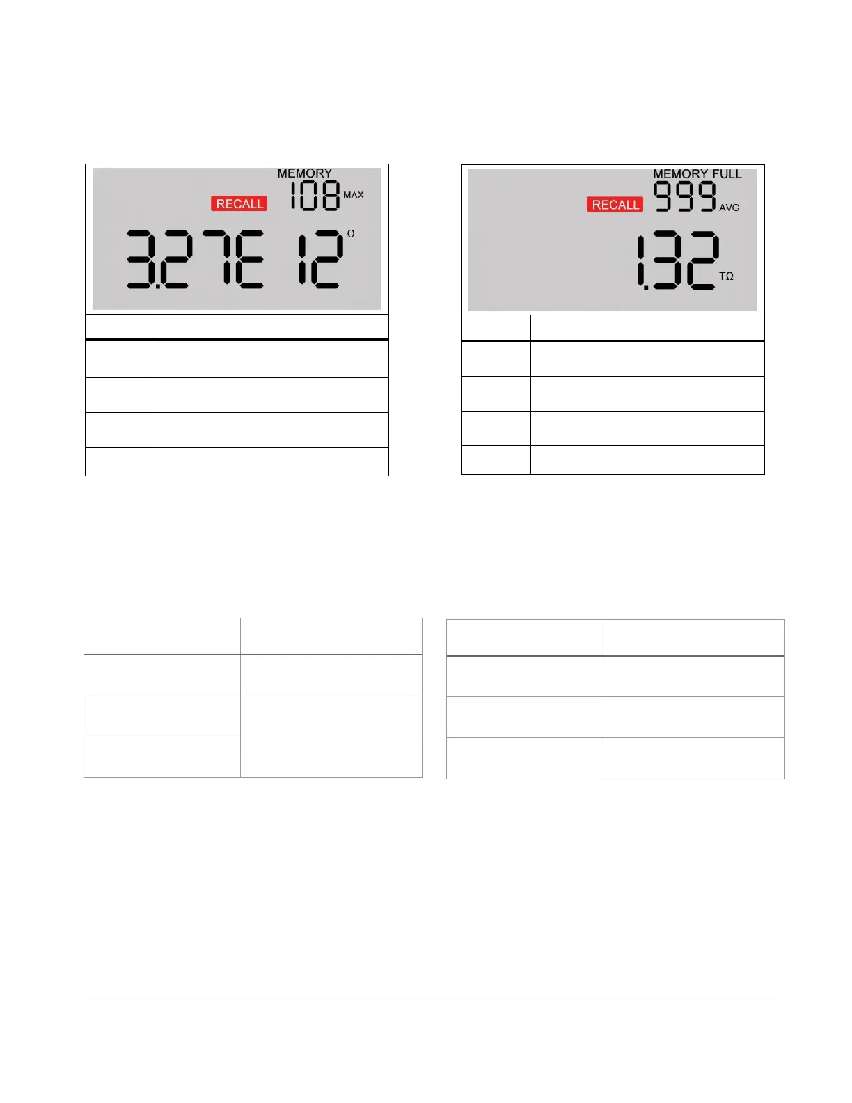
Tables 8 and 9 are lists of visible readings and what the symbols mean when accessing the memory:
Table 8. Display in scientific format Table 9. Display in ohmic format
Test Voltages
In order to make a resistance measurement, a test voltage is being applied. Tables 10 and 11 list the applied
test voltage for each resistance range:
Electrification Period
When making a resistance measurement, the meter needs a period of time to stabilize and make sure the
measurement displayed is the most accurate measurement.
Table 12 list the electrification period (EP) for each resistance range:
Indicates how many data sets in
memory
The highest measurement stored in
memory (MIN also available)
Measurement in ohms
1.00E12 = 1
teraohm
Access to internal memory
The average of all measurement in
memory
Measurement in teraohms
1 teraohm = 10
12
ohms
Access to internal memory
Table 10. Applied Test Voltage in AUTO, CONTINUOUS
AND AUTO MANUAL Mode
Table 11. Applied Test Voltage in MANUAL Mode