3 Q80S_2014
24Vac
230Vac
F2
J5
J1
JP4
JP5
JP6
JP8
JP7
1 2 3 4 5 6 7 8 9 10 11 15 16 17 18 19 20
JP1
JP2 JP3
K3
K1
K4
22
21
T2
U1
TR2
C8
C21
C24
ALIM.
230Vac
5A
230Vac
JP9
12 13 14
FR1
V1
FR2
PROTECO S.r.l. Via Neive, 77 - 12050 Castagnito (CN) ITALY Tel. +39 0173 210111 - Fax +39 0173 210199 info@proteco.net - www.proteco.net
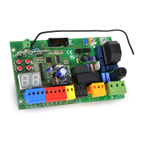
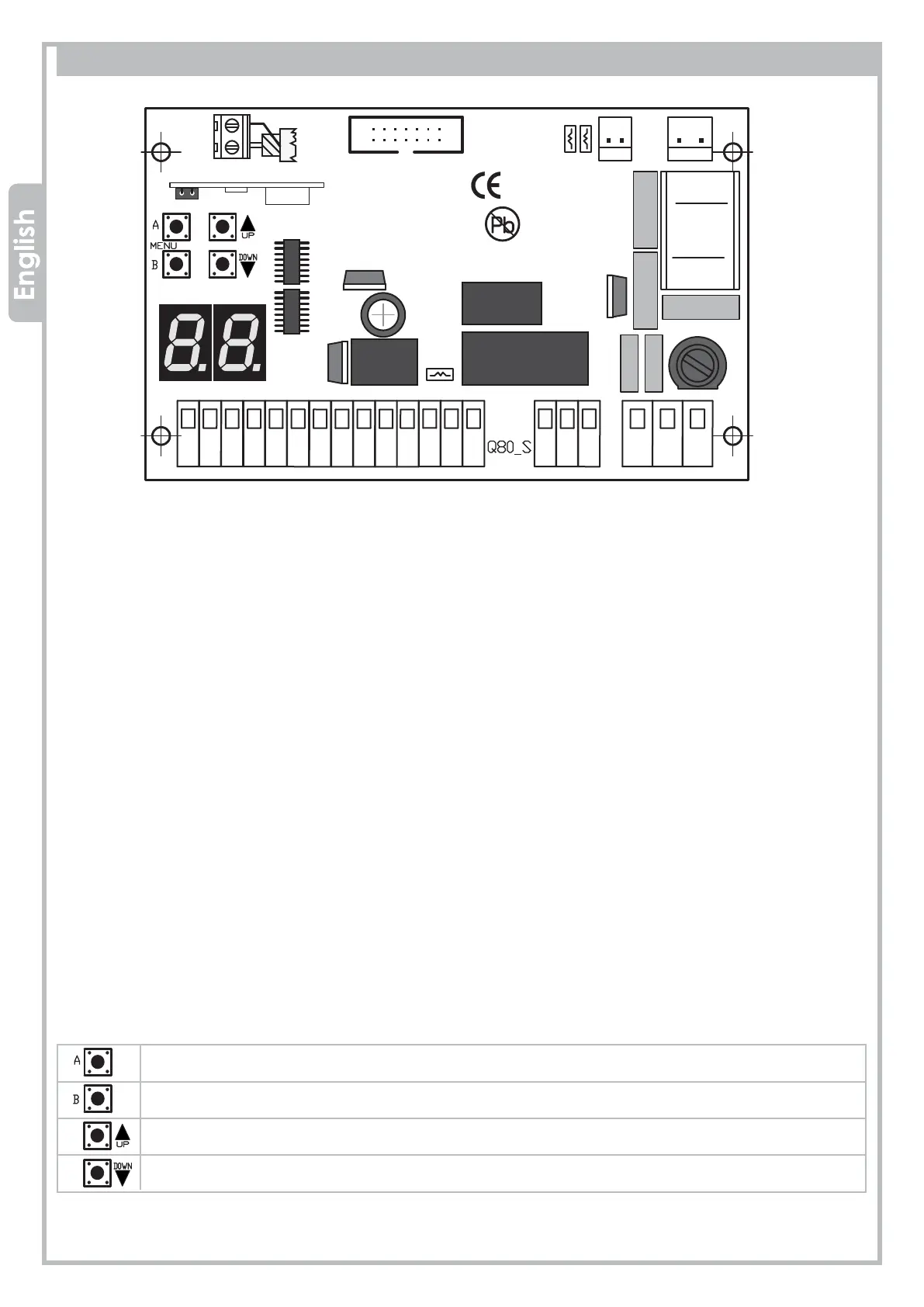
2. WIRING DIAGRAM and COMPONENTS
Display BUTTONS Legend
ENTER
EXIT
INCREASE or START command (when not programming)
DECREASE or PEDESTRIAN START command (when not programming)
DISPLAY = segments display
J1 = radio module
J5 = plug for optional modules
F2 = 230V fuse 5A
FR1 = 24V fuse 1.6A (self-restorable)
FR2 = 24V fuse 0.6A (self-restorable)
V1 = secondary varistor
K1/K3 = motor relay
K4 = blinker relay
TR2 = filter
JP1 = AERIAL terminal block
JP2 = secondary transformer plug 24Vac
JP3 = main transformer plug 230Vac
JP4 = CONTROLS terminal block
JP5 = PHOTOCELLS terminal block
JP6 = BLINKER terminal block
JP7 =
input Motor
JP8 =
input LIMIT-SWITCH
JP9 = 230V MAIN power/earth terminal block