1 2 3 4
ON ECE
SW1
1 2 3 4
ON ECE
SW1
1 2 3 4
ON ECE
SW1
1 2 3 4
ON ECE
SW1
1 2 3 4
ON ECE
SW1
11 Q80S_2014
J5
24Vac
230Vac
J5
J1
JP4
JP5
JP6
JP7
JP8
JP9
1 2 3 4 5 6 7 8 9 10 11 12 13 14 15 16 17 18 19 20
JP1
JP2 JP3
22
21
TR2
C8
C9
C21
C24
ALIM.
230Vac
5A
230Vac
1 2 3 4
ON ECE
SW1
JP6
FLASH
24V ac
10 11
PROTECO S.r.l. Via Neive, 77 - 12050 Castagnito (CN) ITALY Tel. +39 0173 210111 - Fax +39 0173 210199 info@proteco.net - www.proteco.net
3.9.1 2ND RADIO CHANNEL settings
Note: to use the MRX04 module as a 2nd radio channel, you need to save the corresponding radio code.
Please refer to RADIO menu, parameter .
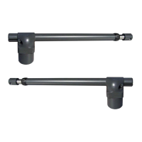
Select the AUX module settings with SW1 dip-switch-block:
STABLE switch
Electric contact closes every time you press the remote control.
To select this mode, please set the dip-switches on the module as shown:
1= ON 2= OFF 3= OFF Dip-switch 4 is non influential.
BISTABLE switch – Toggle Mode
Electric contact closes or opens every time you press the remote control.
To select this mode, please set the dip-switches on the module as shown:
1= OFF 2= ON 3= OFF Dip-switch 4 is non influential.
TIMER mode
Electric contact closes when you press the remote control and stays
closed for 90 seconds.
To select this mode, please set the dip-switches on the module as shown:
1= ON 2= ON 3= OFF Dip-switch 4 is non influential.
3.9.2 CONTROL LIGHT settings
You can use the MRX01 module to control an indicator light.
The electric contact stays closed, so the light stays on, during all the
opening-closing cycle.
To select this mode, please set the dip-switches on the module as shown:
1= OFF 2= OFF 3= ON Dip-switch 4 is non influential.
3.9.3 COURTESY LIGHT settings
You can also use the MRX01 module to control a courtesy light when the gate
is operating. The electric contact closes since the gate starts operating till 90
seconds after the gates stops.
To select this mode, please set the dip-switches on the module as shown:
1= ON 2= OFF 3= ON Dip-switch 4 is non influential.
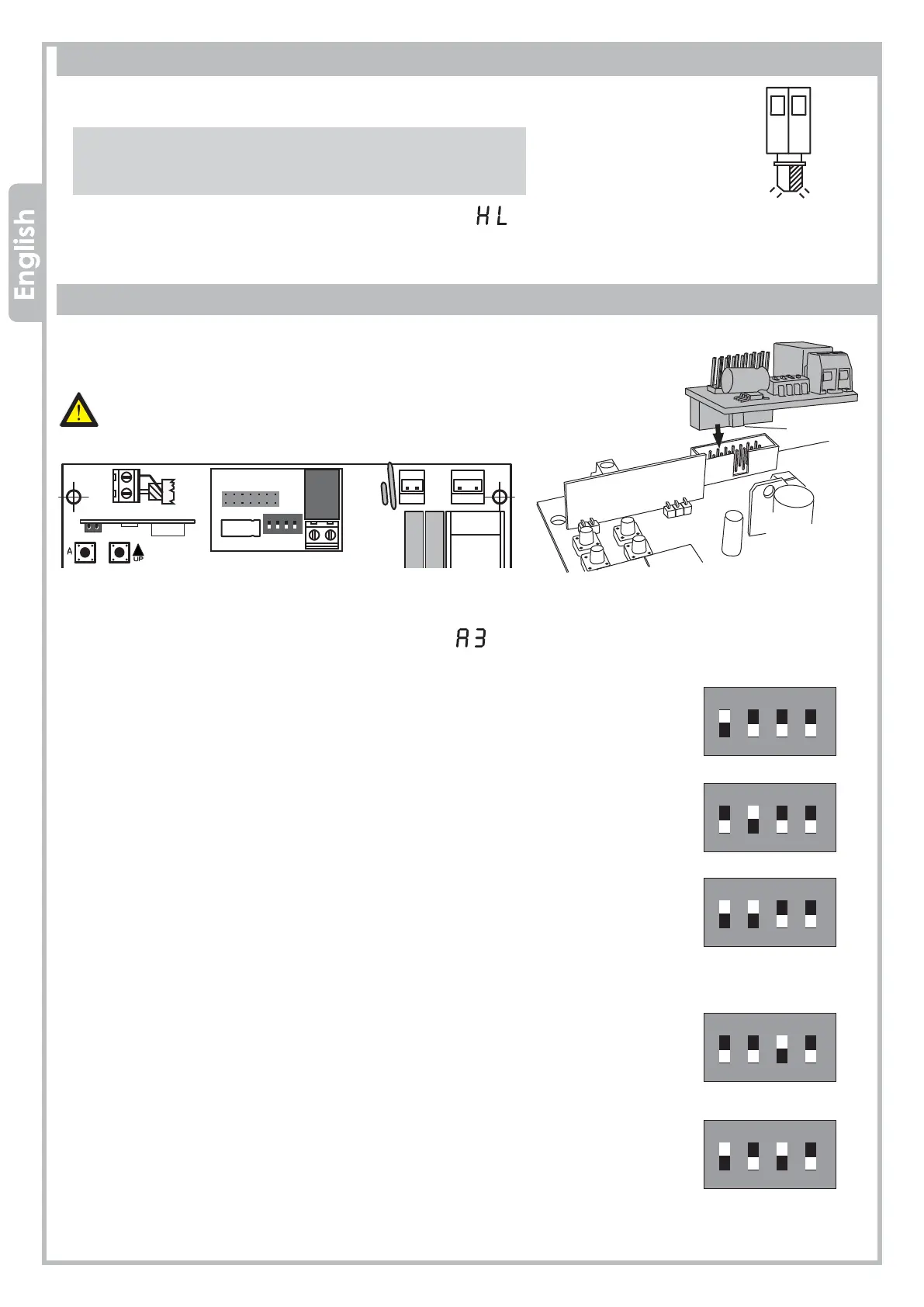
3.8 BLINKER wiring
You can wire a flashing light (20W max) to 10 - 11 terminals on JP6
terminal block.
The flashing light will behave as follows:
• QUICK flashing → the gate is OPENING
• SLOW flashing → the gate is CLOSING
• STILL light on → the gate is in PAUSE TIME before the
automatic closing
Note: You can select the kind of flashing light with
parameter in the FUNCTIONS menu.
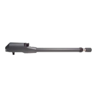
Additional
module
MRX01
3.9 AUX/2ND RADIO CHANNEL module
Driving
slot
Plug the additional MRX01 module (optional) into J5 connector,
please pay attention to the module’s orientation as shown in the picture.
Before setting the dip-switches SW1 on the AUX module,
make sure that the control panel is disconnected from any
power supply.