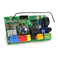
JP6
FLASH
24V ac
10 11
JP7
M1
PED
COM
15 16 17
J5
JP1
22
21
JP2
JP3
JP4
START
STOP
PED
1 2 3 4
JP5
5 6 7 8 9
RX -24V
TX - RX +24V
Test Photo TX -24
FOTO
FTAP
JP9
18 19 20
F
N
5 Q80S_2014
JP8
12 13 14
PROTECO S.r.l. Via Neive, 77 - 12050 Castagnito (CN) ITALY Tel. +39 0173 210111 - Fax +39 0173 210199 info@proteco.net - www.proteco.net
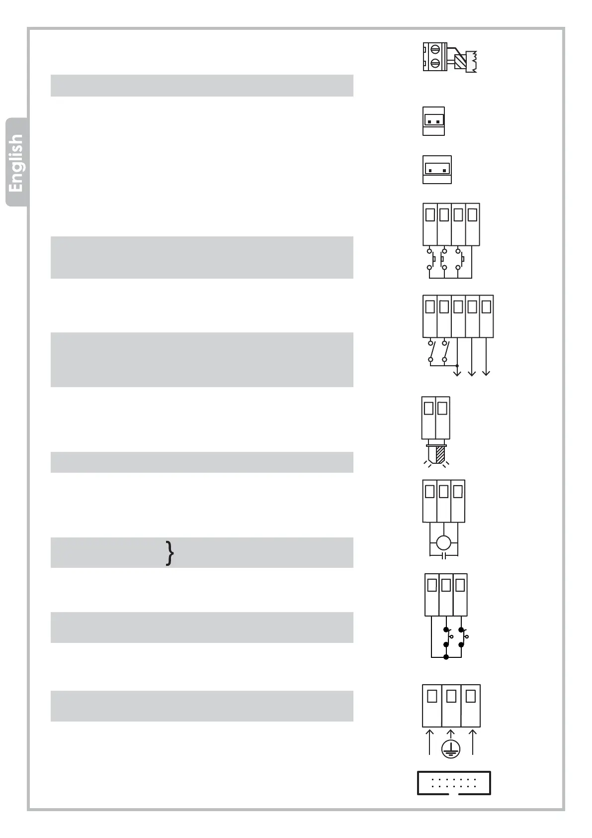
JP1 = AERIAL terminal block
21 aerial cable (SIGNAL)
22 aerial cable (EARTH)
JP2 = TRANSFORMER secondary plug 24Vac (red wires)
JP3 = TRANSFORMER main plug 230Vac (black wires)
JP4 = CONTROLS terminal block
1 START command (N.O. contact)
2 STOP command (N.C. contact)
3 PEDESTRIAN START command (N.O. contact)
4 NEUTRAL for controls
JP5 = PHOTOCELLS and SAFETY DEVICES
5 CLOSING PHOTOCELLS terminal (N.C. contact)
6 OPENING PHOTOCELLS terminal (N.C. contact)
7 Photocells RECEIVER power supply -24V
8 Photocells RECEIVER/TRANSMITTER
9 Photocell TRANSMITTER power supply -24V
JP6 = BLINKER terminal block
10 BLINKER power supply 24Vac
11 BLINKER power supply 24Vac
JP7 = MOTOR terminal block
15 OPENING LIMIT-SWITCH
16 NEUTRAL terminal MOTOR M1
17 CLOSING LIMIT-SWITCH
JP8 = LIMIT-SWITCH terminal block
12 NEUTRAL-
13 OPENING LIMIT-SWITCH
14 CLOSING LIMIT-SWITCH
JP9 = 230V MAIN POWER/EARTH terminal block
Pole disconnect means must be incorporated in the fixed
wiring to the control panel
J5 = plug for optional modules
OPEN
CLOSE
FC OPEN
OP PHOTO
PHOTO
NEUTRAL
P
FC CLOSING