
P
Phillip BergAug 19, 2025
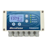
Why does my Pulsafeeder Controller display a “No Flow” alarm message?
- BBradley EscobarAug 19, 2025
The "No Flow" alarm on your Pulsafeeder Controller can be triggered by several issues. First, ensure adequate water flow (at least 1 GPM or 3.8 LPM) through the flow assembly. Also, verify that the flow switch wiring or connector isn't loose. The flow switch may be stuck, so clean the sensor mechanicals. A clogged flow assembly can also cause this, so clean the inside of the assembly. If a flow switch is not used, make sure the flow switch input jumper is installed.