EasyManua.ls Logo

Pulsafeeder MicroVision EX - User Manual

Default Icon
38 pages
Print Icon
To Next Page IconTo Next Page
Loading...
72-900-06 Rev. F
Page 1 of 38
MicroVision
EX
MICROPROCESSOR – BASED
WATER TREATMENT
CONTROLLER
Installation Operation Manual

Table of Contents

Other manuals for Pulsafeeder MicroVision EX

Questions and Answers

  • D
    Daniel MillerAug 4, 2025
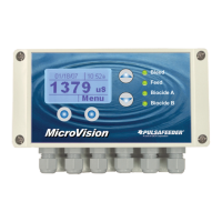
    What to do if my Pulsafeeder MicroVision EX displays a 'Flow Switch Alarm' message?
    • D
      david70Aug 4, 2025
      If your Pulsafeeder Controller displays a 'Flow Switch Alarm' message, it could be due to several reasons. First, ensure that there is enough water flow through the assembly, maintaining at least 1 GPM (3.8 LPM) of flow. Also, check the flow switch connections to make sure they are secure. The flow switch might be stuck, so clean the flow switch sensor mechanical parts. Another possibility is that the flow assembly is clogged, requiring you to clean inside the flow assembly. Finally, verify the flow switch input jumper and install it if the flow switch is not in use.
  • K
    Kevin HamiltonAug 9, 2025
    How to troubleshoot a Pulsafeeder MicroVision EX Controller that does not power up?
    • L
      Larry RobertsonAug 10, 2025
      If your Pulsafeeder Controller doesn't power up, start by ensuring that the correct voltage is supplied to the controller. Check the circuit breaker that supplies power to the controller. Also, inspect and replace any blown fuses. Finally, check the ribbon cable that connects the upper and lower PC boards inside the controller.
  • C
    Chad GonzalezAug 15, 2025
    What to do if my Pulsafeeder MicroVision EX Controller displays a 'Limit' alarm message?
    • S
      Sarah GreenAug 15, 2025
      If your Pulsafeeder Controller displays a 'Limit' alarm message, it may be because the programmed limit timer is set too short; adjust the limit timer value to a longer duration. Another cause could be a clogged bleed valve or drain, so clean the valve or drain. Lastly, the bleed valve might be faulty, requiring you to replace the bleed valve.
  • M
    Morgan WadeAug 21, 2025
    Why does my Pulsafeeder Controller display a 'Probe Comm' alarm message?
    • B
      Barbara JonesAug 21, 2025
      If your Pulsafeeder Controller displays a 'Probe Comm' alarm message, start by checking the probe connections to ensure they are secure. A bad conductivity probe could also be the reason, so consider replacing the probe.
  • J
    Jason GreenAug 27, 2025
    What does it mean when my Pulsafeeder MicroVision EX Controller displays a 'Bleed Limit' alarm message?
    • R
      ritagarnerAug 27, 2025
      If your Pulsafeeder Controller displays a 'Bleed Limit' alarm message, it might be due to the Conductivity Limit timer being set too short, so adjust the limit timer. Another potential cause is a bleed valve/drain failure, in which case you should clear any obstruction around the drain.

Summary

General Warnings and Safety

Controller Installation Guide

Location Selection Criteria

Guidance on selecting an appropriate mounting location for the controller.

Mounting Hardware Recommendations

Instructions for selecting and using appropriate mounting hardware.

Sensor Installation Procedures

Conductivity, pH, and ORP Sensors

Details the installation of conductivity, pH, and ORP probes.

Flow Switch Installation Guide

Instructions for installing the flow switch in a vertical position.

Important Symbol Information

Electrical Wiring Guidelines

Digital Input Configuration

Water Meter & Drum Level Inputs

Instructions for connecting water meter and drum level inputs.

4-20 mA Inputs;Outputs Setup

Details connecting sensors with 4-20mA output and using 4-20mA inputs.

Calibrating PTSA Probe

Controller Programming Overview

Main Menu Options

Configure Menu Options

Digital Input Configuration

Configure drum level and water meter inputs.

Password Setting and Security

Software Version and Factory Reset

Factory Reset Functionality

Resetting all controller parameters to their factory default values.

Settings Menu: Conductivity

Conductivity Probe Calibration

Guide to calibrating the conductivity probe using in-stream method.

Settings Menu: pH and ORP

pH and ORP Probe Calibration

Steps for calibrating pH and ORP probes using in-stream or standard solutions.

Timer Modes Overview

USB Data Management

Factory Default Settings

Troubleshooting Common Issues

Controller Maintenance Schedule

Product Specifications

Factory Service Policy and Warranty

Pulsafeeder MicroVision EX Specifications

General IconGeneral
TypeMicroprocessor-based controller
Power Supply100-240 VAC, 50/60 Hz
Inputs4-20mA, Pulse, Digital
OutputsRelay, 4-20mA
DisplayLCD
EnclosureNEMA 4X
CommunicationModbus RTU
Relative Humidity5% to 95% non-condensing

Related product manuals