72-900-06 Rev. F
Page 7 of 38
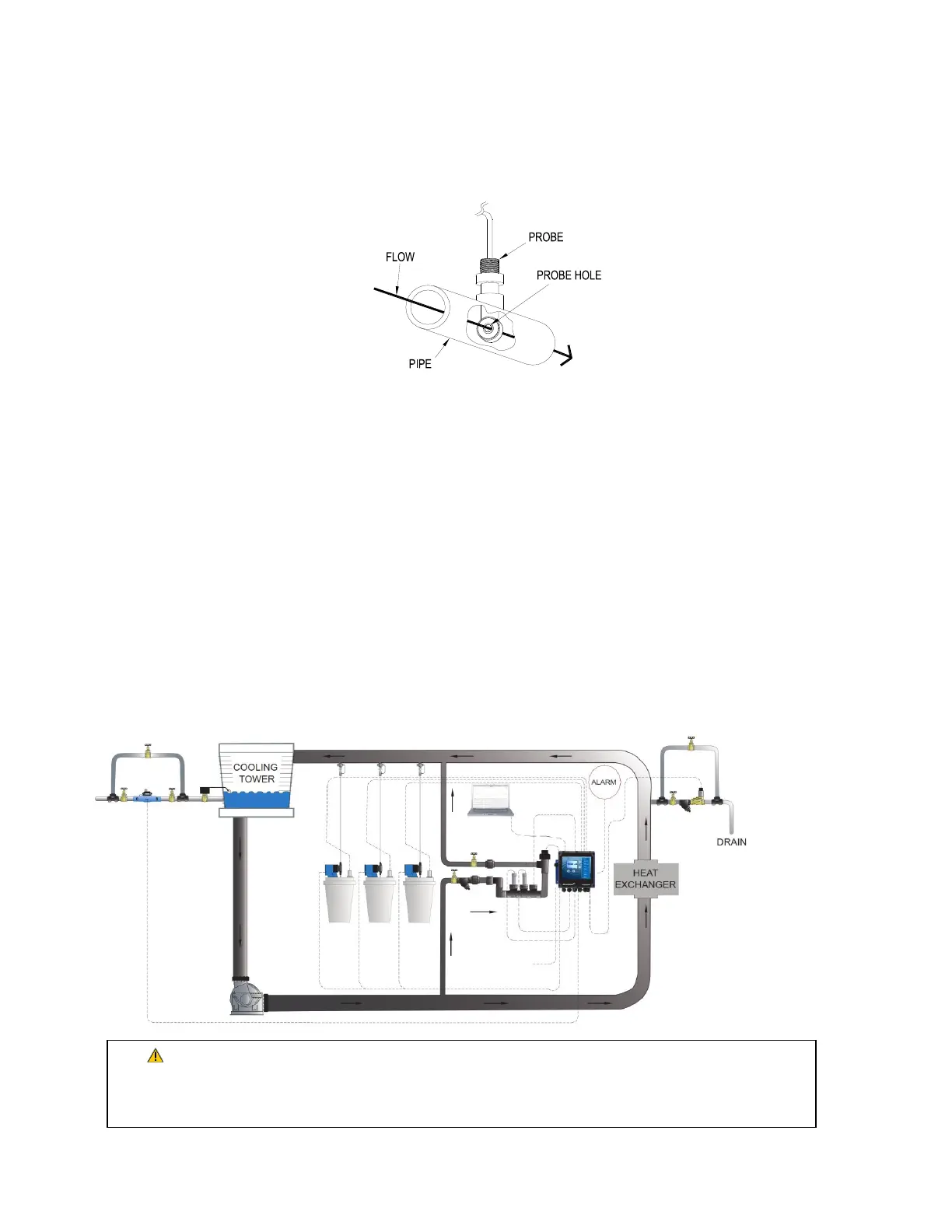
3.4 Sensor Installation
Conductivity
The controller is supplied with a temperature compensated toroidal conductivity probe
installed in a tee. The probe should only be installed where adequate flow is going around
and through the hole in the center of the probe in the tee provided.
pH and ORP
When ordered as a pH or ORP model the controller will be supplied with standard pH and
ORP probes. The probes are supplied installed in a tee. The probes should only be installed
where flow between 1 and 5 GPM is going around the probe.
Flow Switch
If the controller is provided with a flow switch, install the flow switch so that flow enters
into the bottom of the flow switch tee, and out the side of the tee. The flow switch must
always be installed in a vertical position so that the sensor wire is coming out of the top,
and the internal (red) flow shuttle is able to rise when there is flow and drop when there is
no flow. The flow switch is activated when 1 GPM (3,8 LPM) is going through it, and is
deactivated when the flow drops below 1 GPM (3,8 LPM).
3.5 TYPICAL INSTALLATION
Over pressurization of the plumbing can occur when cooling tower is higher than the
piping and controller system. Ensure all pressures have been accounted for. Verify piping
and sensor allowable temperatures are above maximum temperatures of the system.