72-910-16 Rev. N
Page 13 of 43
for conduit power and load connections. Supply (input) power is connected via PL5
located on the relay board (Fig. 6). The top part of this terminal block is removable to
allow for easy access to the connector’s three (3) screws.
Make sure that all conduit connections are water tight.
The four (4) output relay terminal blocks are identified as: PL1 (Bleed), PL2 (INHIB), PL3
(BIO A), and PL4 (BIO B). These terminal blocks can be removed in the same manner
as PL5. The Bleed relay has a N.O. and a N.C. connection, the others are only N.O.
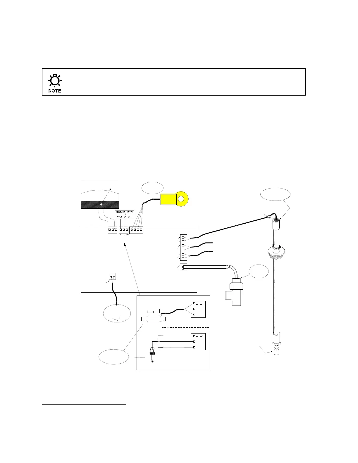
5.3 LOW VOLTAGE CONNECTIONS
The low voltage connections are found on the low voltage (right side) board (Fig. 6).
Use 22-24 AWG (,76 mm²) wire for: flow switch, drum levels, dry alarm, and water
meter connections . These signal wires must be run separate from AC power lines.
J10
J4
J5
DRY ALARM
RELAY (N.O.)
J3
J2
+5V
DRUM LEVEL
DETECTORS
CONTACT
METER
+5V
GND
J3
+5V
J3
OR
TOP
BOARD
WATER METER
TYPES
GND
BLK
W METER
ALARM
ORG
BRN
RED
DRUM LEVEL
INHIB
BIO A
BIO B
FLOW
COND SENSOR
HALL EFFECT
TOROIDAL
PROBE
FLOW
SWITCH
(3X)
FLOAT
04-000-18
16-171-81-2 26" (,66m)
04-350-91
16-171-81-1 26" (1,17m)
16-171-81-4 26" (1,52m)
+ -
J8
4-20mA
mA
4
20
8
+
-
Fig. 7
Trained service personnel are required for all electrical connections. This product does not contain operator
serviceable parts.