10 QSC Audio Products, LLC
Figure 1.8. The PL380 service
fixture
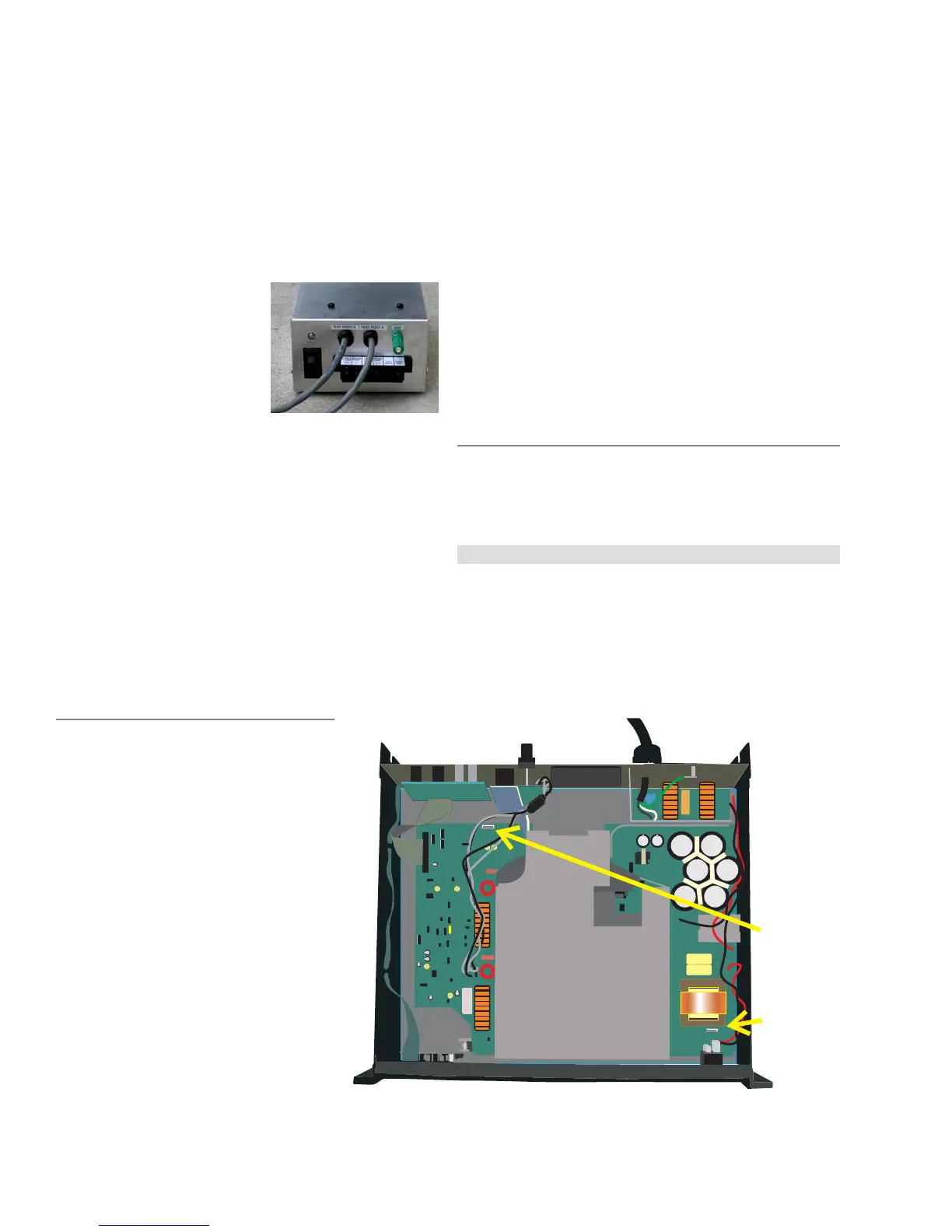
Figure 1.9. Locations of Test Point A and Test Point B
1.5 PL380 Service Fixture
With its class D output section, the PL380 amplifier differs from all
previous QSC stand-alone models, which up to now have used
linear output circuitry in either a class AB configuration or a class
AB-based class G or H one.
To the end user, these differences should not be apparent, except
that he or she may notice that
such a high-power amplifier does
not generate much heat and
appears to consume much less
electricity than might be
expected. The PL380 amplifier
should behave sonically like a
high-quality, high-power audio
amplifier.
Being a class D amplifier, the
PL380 uses pulse-width modula-
tion to allow output transistors that are either fully on or fully off to
produce varying output voltages. To reduce noise, the clock for the
output sections’ modulators is synchronous with the power supply’s
clock. However, that interdependence makes testing and trouble-
shooting one section of the amplifier without the other impossible.
This is the reason for the PL380 service fixture (Figure 1.8). It is
necessary for many of the procedures described in Chapter 2’s
section on the PL380 test procedure, and in Chapter 3’s sections on
PL 380 troubleshooting.
Figure 1.12 shows the schematic for the PL380 service fixture. The
fixture is available for purchase from QSC Technical Services.
Functions of the service
fixture
• Substitutes for the amplifier’s house-
keeping supply. The housekeeping supply
powers the clock, power supply switching,
and modulation circuitry. The fixture allows
you to operate and check these key areas of
the amplifier’s circuitry even without its being
connected to the AC mains.
It also allows you to operate the amplifier for
testing and troubleshooting at low AC mains
voltages that would be less likely to cause
damage if a fault exists.
• Monitors the ±15-volt rail currents. The
terminal strip on the service fixture provides
precision voltages that are analogous to the
currents drawn by the positive and negative 15-
volt supply rails. The voltages are scaled to 1
volt = 1 ampere. This is useful for detecting
abnormal situations such as defective op amps or other circuitry
that could cause abnormally high or low current demand.
• Monitors the +5-volt suppy. The 5-volt regulated supply
powers the clock and logic circuitry. Because it is derived from
other higher voltage DC supplies, the presence of the voltage on
the screw terminal indicates that they also are functioning.
• Verifies clock switching. The “Sync Sig” terminal should
carry a 250 kHz pulse train signal. Its presence verifies that the
clock oscillator and divider circuits are operating. Because of the
cables connecting the fixture to the amp, the pulse train will
tend to be messy, with significant ringing. Therefore, the signal
is useful only to verify the operation of the amp’s circuitry.
Hooking up the service fixture
These steps describe how to set up the service fixture and connect
it to the PL380.
Prepare the service fixture
1. Set the service fixture on the right side of your test bench work
area, with the screw terminals and hookup leads facing toward
you. Setting the fixture this way makes it nearly impossible to
connect the hookup leads the wrong way.
TEST POINT A
TEST POINT B
Test Point B
Test Point A

 Loading...


