PL3 Series Service Manual 43
TD-000274-00 Rev. A
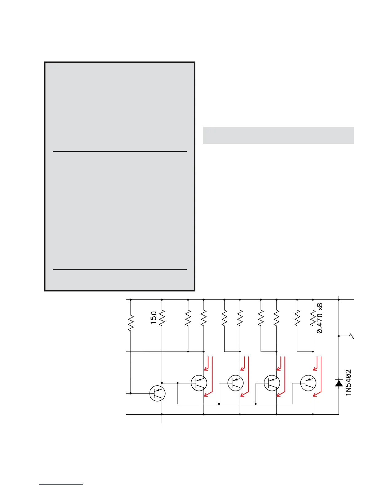
Figure 3.11. Identify damaged transistors by measuring resistance across the collector and emitter.
• U19, a SG3525AN pulse-width modulation controller; it may be
damaged by high currents shorted through U18 or by overvoltage
on the supply rail.
• U14, a 556 dual timer; powered from the 5V reference voltage
output of U19, it may be damaged when the SG3525AN fails.
• U13 has fairly high supply voltage ratings and should rarely fail.
Audio Output: Troubleshooting and replacing
damaged output transistors
Overview
When an output transistor fails, it will usually become a short circuit
across its base, emitter, and collector terminals. A short circuit in
one device often cause another to fail as well.
If an output transistor shorts:
• The driver transistor connected to it will probably also fail (Q26,
Q27, Q71, or Q72).
• Certain transistors tend to fail or short in pairs: Q39 and Q40,
Q36 and Q37, Q84 and Q85, or Q81 and Q82.
• Others may tend to fail or short in groups of four: Q28, Q29, Q34
and Q35; Q73, Q74, Q79 and Q80.
PLC Power Supply
Restoration Kit
The PLC power supply restoration kit contains most often
needed parts for restoring a faulty power supply in a PL325
amplifier.
PLC Series Power Supply Restoration Kit (QSC
part number: SG-000060-00)
Part Number Description Reference Qty.
QD-000169-00 XISTOR IGBT TO-247AC 600V 55A Q96 and 97 2
QD-000042-00 DIODE RECT ULTRAFAST 400V 3A D70 and 71 2
QD-000108-30 DIODE SMT SWITCH 200V .2A 50NS D78 and 79 2
QD-000113-30 DIODE ZNR 10V 5% D66 1
RE-001003-30 RESISTOR SMT 10 OHM 1% 1206 R358 and 359 2
RE-003921-30 RESISTOR SMT 39.2 OHM 1% R349 1
RE-000210-NR THERMISTOR NTC 15A R324 1
IC-000134-00 IC CMOS HV DRVR IR2110 U18 1
IC-000024-00 IC REG PWM 40V 0.1A SG3525A U19 1
IC-000053-30 IC LIN SMT DUAL TIMER LM556 U14 1
IC-000054-30 IC LIN SMT QUAD COMP LM339AM U13 1
NA Technical Support CD NA 1
Needed for PL340
The PL340 amplifier uses the same parts except for the
IGBTs, which require a higher current rating.
Part Number Description Reference Qty.
QD-000315-00 IGBT,600V,75A,IXGR60N60C2,TO-247 Q96 and 97 2
failure should be rare (when
correctly assembled) but when
an IGBT fails, it usually damages
the following parts:
• Q96 and Q97 (IGBTs generally
fail in pairs)
• Gate drive coupling compo-
nents D78, D79, R358, R359;
check them after removing
blown IGBTs.
• U18, the IR2110 high-side
gate driver; damage occurs
from high current when low-
side IGBT, Q97, shorts to
PRI_HI. Such current surges
typically also damage the
gate drive coupling compo-
nents noted above.
Measure
here
R
Measure
here
R
Measure
here
R
Measure
here
R
If = approx. 0.4 : transistor is blown
If = 0.7 : transistor is good
R
R
Ω
Ωapprox.
3.2 PL325 and PL340: Symptoms, causes, and remedies (continued)

 Loading...


