31
TD-000472-00-B
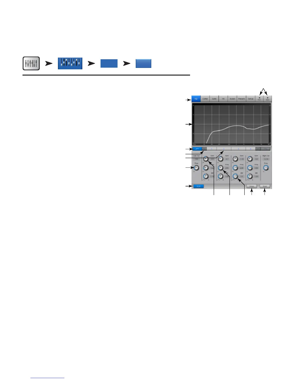
Input Channel – EQ
Controls and displays the settings for Input Channel equalization.
Refer to — Figure 20 –
1.
EQ
Tab
– Selects the EQ screen.
2.
Parametric EQ Graph
– A graphic representation of the equalization curve based on
the EQ settings. When the EQ is engaged, the trace changes from black to white.
•
EQ Graph Vertical Scale
– Represents audio level from -20 dB to +20 dB.
•
EQ Graph Horizontal Scale
– Represents frequency from 20 Hz to 20 kHz.
3.
Low and High Cut Filter Buttons
– These filters cut frequencies below or above the
frequency set by the corresponding Freq control.
4.
Low and High Shelf Filter Buttons
– Changes EQ Band 1 and Band 4 from
parametric filters to shelving filters. When a shelf filter is engaged, the Bandwidth control
is not available.
5.
Frequency Bands 1, 2, 3, and 4 Buttons
– Engages / disengages the associated
parametric EQ band. Four overlapping frequency ranges, each adjustable from 20 Hz to
20 kHz. Each band has an associated Gain, Frequency, and Bandwidth control.
6.
Freq Control Knob
(Low and High Cut) – Sets the frequency of the low and/or high cut
filter as measured from a point 3 dB below 0 or unity.
7.
EQ In Button
– Engages the equalizer.
8.
Gain Control Knob
– Adjusts the gain at the frequency setting of the associated EQ
band. Range of -15 dB to +15 dB.
9.
Freq Control Knob
(Frequency bands 1 – 4) – Sets the center frequency of the associated EQ band. If the Shelving filter is engaged, the Freq
control sets the frequency of the shelf filter at a point 3 dB above or below 0 or unity.
10.
Bandwidth Knob
– Adjusts the bandwidth of the associated EQ band. The Bandwidth is measured in Q. When the Self Filter is engaged, the
Bandwidth knob is hidden.
11.
Simple Button
– Hides the Low Cut, High Cut, Frequency, and BW controls. Does not effect existing settings.
12.
Reset Button
– Sets all the EQ controls to their factory default position.
13.
Prev / Next Buttons
– Navigates to the next or previous channel. The buttons cycle through the Input, playback, record, and FX channels, then
loops back to Input 1. If you start in the Auxes, the buttons cycle through the Auxiliary outputs and the Main L/R channels.
Home Select an
Input Bank
Touch Select
Button
Select
EQ Tab
EQIn 2
Inputs 1-8
— Figure 20 —
2
3
4
5
1
6
7
 Loading...