page 21
3. Re-connect the power to BOTH base stations. The LED on the front of the lane 1 base station will
turn solid red. The LED on the lane 2 base station will turn solid GREEN.
4. Now follow Step 14 to register ALL the headsets to the system
using either base; the process is identical to that for single lane.
5. Now follow Steps 15 to 19 in the manual to set up the audio levels
at each order point. The setup process is done twice, separately,
once for each lane. Note - in tandem lane configuration, there is no
‘multiple-order taker’ feature.
You will be asked to confirm whether the site is operating DUAL or
TANDEM lane. If you have selected tandem, you will be required to
record a ‘Pull forward’ message. Please go to Appendix I to read how to
do that.
6. Once you’ve finished selecting mode and audio levels and recorded
the pull forward message in the case of tandem, press RESET. The
system is ready to be used, and you should explain the headset features
to the customer.
When you place a battery into a headset at the beginning of the day it always defaults to lane 1
runner. Review the table below to understand how to move from lane 1 runner mode.
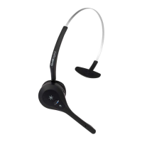
Figure 25 shows the bottom of the base station.
When pressed, the third button from the left engages
‘Single Order Taker’ mode, where a single order taker
operates both lanes. Its default position (off) is one
order taker for each order point.
Figure 25 - Additional data socket & function button
Order taker mode
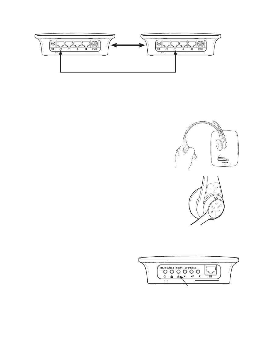
Figure 24 - Connecting dual lane stations
Units must
be at least
45cm or
18” apart
Data link for dual lane operation
Base 1 Base 2