Step 6 Fit the Drive-Thru Module
(Q-P9DTM) into to the order point using
the flanges and four screws. If the DTM
does not fit or cannot be mounted in the
order point, go to Step 10.
Step 7 Install the cable from the DTM in the order
point, through the existing underground conduit(s)
to the likely location of the base station (Q-P9BS)
in the kitchen area. Then, connect both ends of
the cable to the internal and external network
termination boxes. For Cat5 cabled sites refer to
Appendix A, page 10.
Step 8 Plug in the black Cat5 cable and the speaker
and the microphone to their respective sockets on
the DTM as shown.
Step 9 Before connecting the loop to the DTM
ensure you have checked the loop
lead-in wires for continuity. If this test fails, check/
test or replace the loop as required. If the test
is successful, proceed to connect loop lead-in
wires to the screw terminals of the DTM as shown,
remembering to fit the weatherproof cover
provided.
Note: loop wire twists must be maintained
up to the point of connection
page 5
PRO 9 DRIVE THRU MODULE
Q-P9DTM
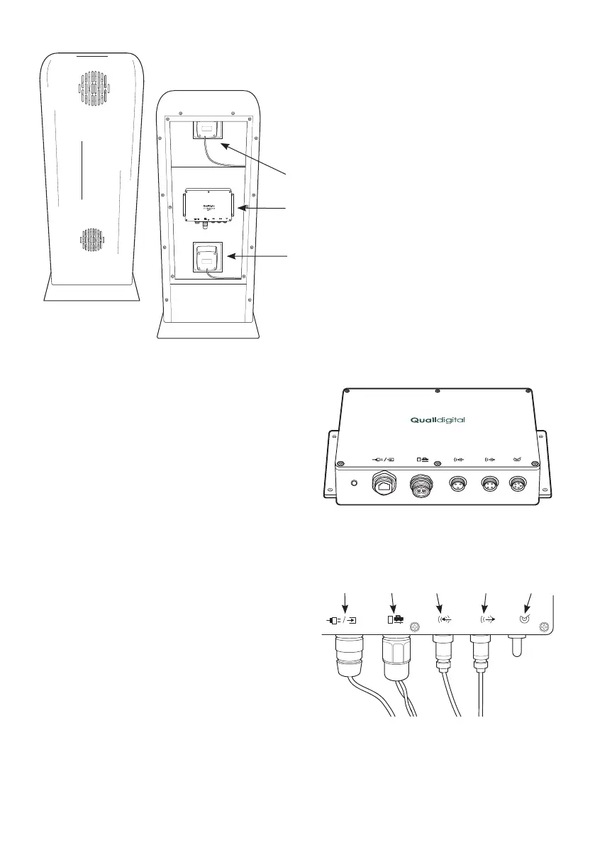
Figure 4 - Pro9 Drive-Thru Module (DTM)
Figure 3 - Order point assembly
Drive-Thru Module
Speaker
Microphone
Figure 5 - Loop connection
Connection
to sonar
Connection
to mic
Connection
to speaker
Connection
to loop
Connection
to base