Step 10 If the order point is physically too small to house the DTM or if the ambient temperature
in the order point might exceed 40°C (104°F) on a regular basis, the DTM can be located internally.
In doing so you will need to cut and remake the speaker and microphone connections using the
Junction Boxes (Q-P9JB) - ordered separately. See Appendix C for this procedure.
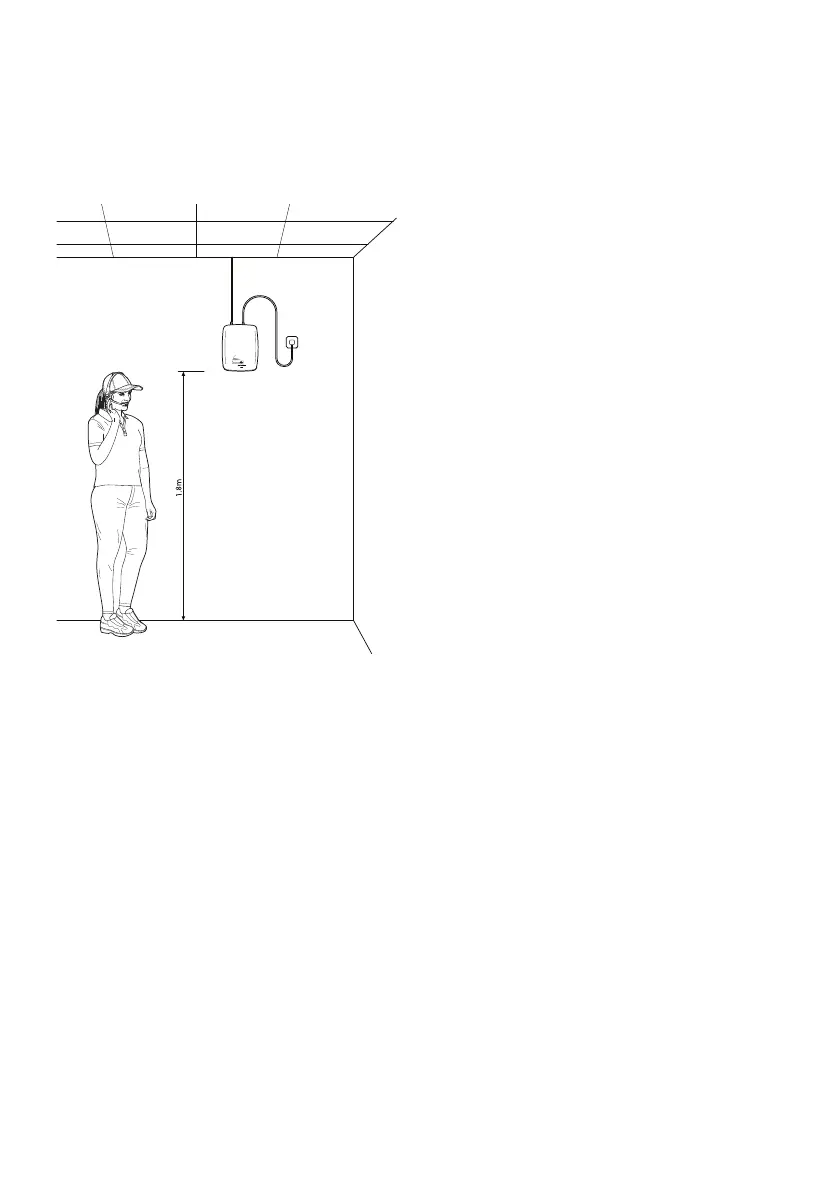
Step 11 Choose a location to mount the base
station with as much clear space around it
to optimize the transmission range. Use the
template to locate the fixing holes. The power
supply should be close by.
Note: there are no user adjustable settings
inside the base station
Step 12 If there is a lane timer and/or a chime speaker to be connected to the system, refer to
Appendix D.
Step 13 Plug in the Cat5 cable from the internal junction box (Q-P9NTINT) into the base station. On
powering up the base station, the speaker in the post will beep four times. This is the system carrying
out checks to ensure that the speaker and mic are connected properly and operational. The LED will
flash amber and then turn constant RED when ready and on standby. If the LED is flashing red or
amber, see ‘Trouble shooting’ on page 25.
page 6
Figure 6 - Positioning the base station