Chapter 1: Components
QXS-656 System
QX and QXS Setup Guide 42
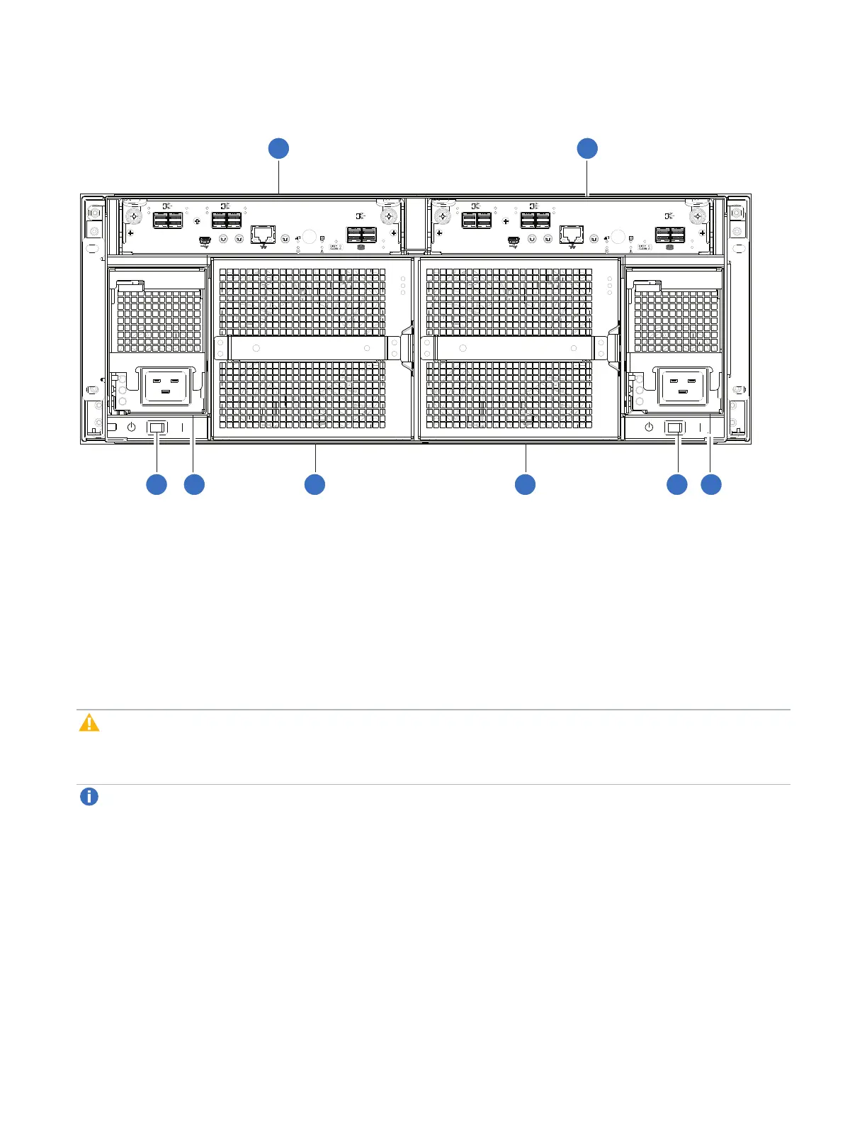
Figure51:QXS-656 RAID Chassis: Rear Panel Layout
CACHE
CLI
CLI
LINK
ACT
S ERVICE−1S ERVICE−2
ACT
LINK
12Gb/s
S
S
A
ACT
LINK
S AS 0 S AS 1
ACT
LINK
ACT
LINK
S AS 2 S AS 3
EXP 0 EXP 1
6Gb/s
S
S
A
LINK 0
LINK 1
12Gb/s
S
S
A
CACHE
CLI
CLI
LINK
ACT
S ERVICE−1S ERVICE−2
ACT
LINK
12Gb/s
S
S
A
ACT
LINK
S AS 0 S AS 1
ACT
LINK
ACT
LINK
S AS 2 S AS 3
EXP 0 EXP 1
6Gb/s
S
S
A
LINK 0
LINK 1
12Gb/s
S
S
A
1
12
3 3
4 45 5
1. ControllerI/OmoduleA
2. ControllerI/OmoduleB
3. ACPowerswitch(qty.2)
4. ACpowersupply(PSU,qty.2)
5. Fancontrolmodule(FCM,qty.2)
The RAID chassis accommodates two controller I/O modules within the chassis (see callouts No.1 and No.2
above). A RAID chassis accommodates two power supply units of the same type, either both AC or both
DC, within the two power supply slots (see two instances of callout No.4 above). Beneath each power
supply is a power supply switch (see two instances of callout No.3 above). The RAID chassis
accommodates two fan control modules (see two instances of callout No.5 above).
Caution:The configurations are dual-controller. Single-controller support is provided only when a
controller fails over to its partner controller. A controller I/O module must be installed in each slot to
ensure sufficient airflow through the chassis during operation.
Note:The chassis support hot-plug replacement of redundant I/O controller modules, fans, power
supplies, and expansion modules. Hot-add replacement of expansion chassis is also supported.