Chapter 6: LEDDescriptions
LEDs for 12-, 24-, 48-Drive Systems
QX and QXS Setup Guide 168
Components for 12-, 24-, 48-Drive RAID Chassis (Rear
View)
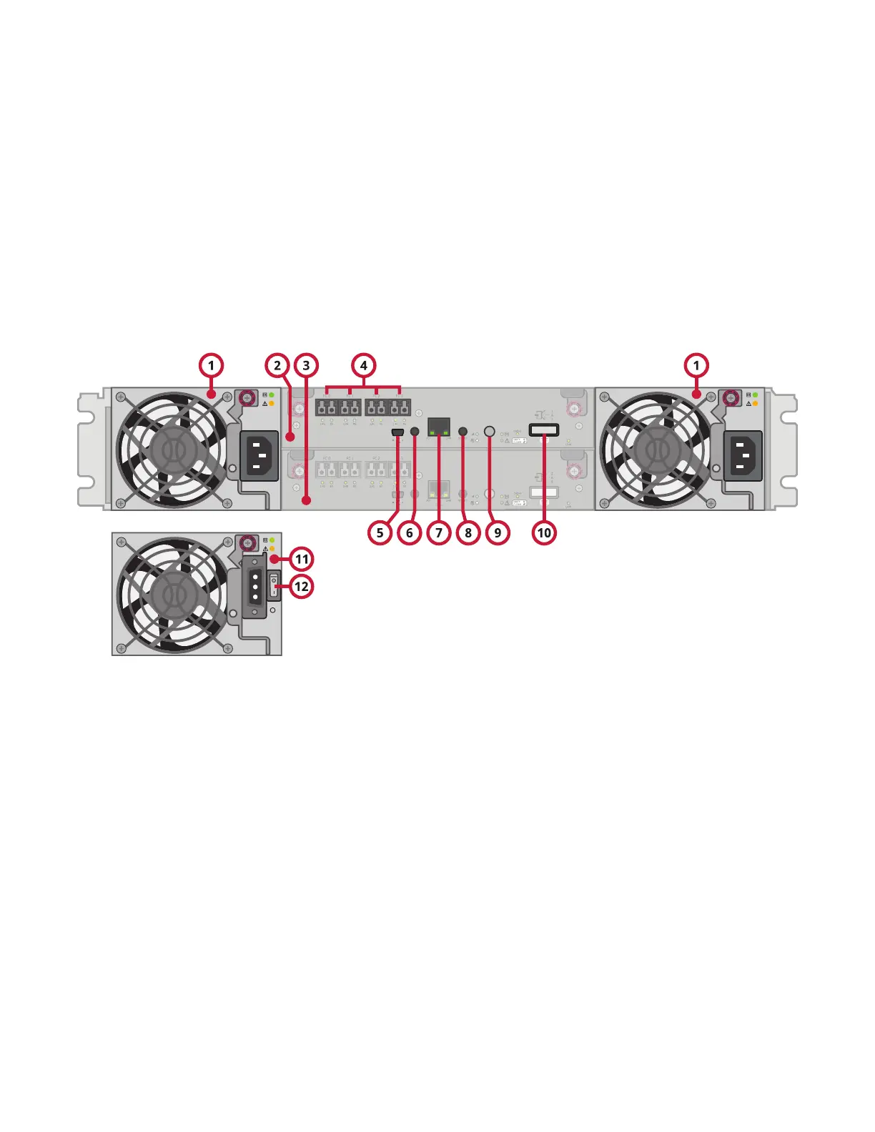
The diagram and table below display and identify important component items that comprise the rear panel
layout of a QXS Storage RAID Chassis . The image shown is a representative example of a RAID Chassis
included in the product series.
Figure119:Example RAID Chassis: Rear panel layout
1. ACpowersupplies
2. ControllermoduleA
3. ControllermoduleB
4. FCports:hostinterface
5. CLIport(USB-TypeB)
6. Reservedforfutureuse
7. Networkport
8. Serviceport(usedbyservicepersonnelonly)
9. Disabledbutton(usedbyengineering/testonly)
10. Expansionport
11. DCPowersupply(2)—(DCmodelonly)
12. DCPowerswitch
A RAID Chassis accommodates two power supply FRUs of the same type (either both AC or both DC)
within the two power supply slots. The RAID Chassis accommodates up to two controller I/O modules of the
same type within the IOM slots.
This section provides descriptions for the different controller I/O modules and power supplies that can be
installed into the rear panel of a QXS Storage RAID Chassis . Showing controller I/O modules and power
supplies separately from the chassis enables improved clarity in identifying the component items called out
in the diagrams and described in the tables.
LED descriptions are also provided for optional expansion chassis supported by the QXS Storage RAID
chassis .