GV58CEU User Manual
TRACGV58CEUUM001 –
8
–
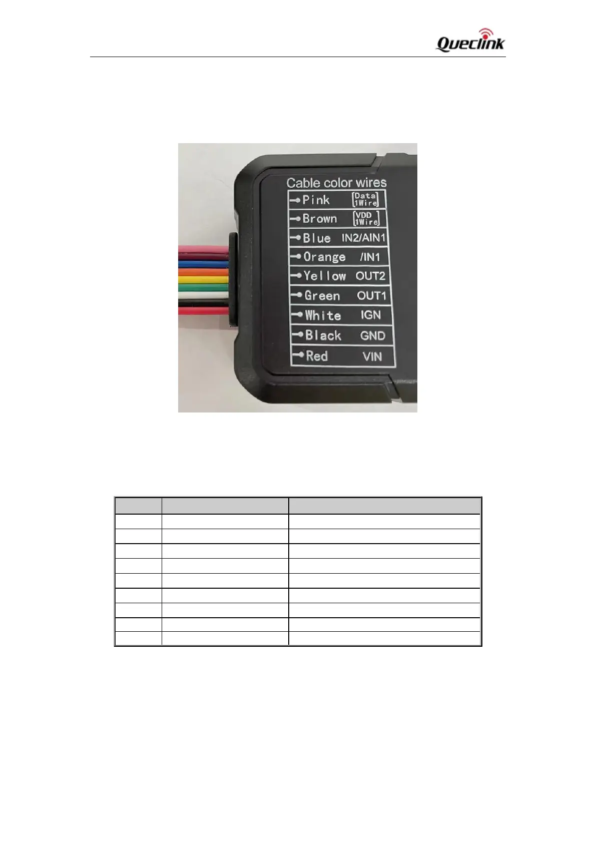
2.2. Interface Definition
GV58CEU has a 9-PIN interface connector. It contains the connections for power, and I/O. The
sequence and definition of the 9-PIN connector are shown in the following figure:
Figure 2: 9-PIN Wire Harness of GV58CEU
Table 3: Description of 9-PIN Connections
1-wire device power output
Digital Input/Analog input, 0V-30V
Digital output, Open drain, 150mA max
Digital output, Open drain, 150mA max
Ignition input, positive trigger
External DC power input, 8V-32V

 Loading...