LTE Standard Module Series
EC25 Hardware Design
EC25_Hardware_Design 56 / 130
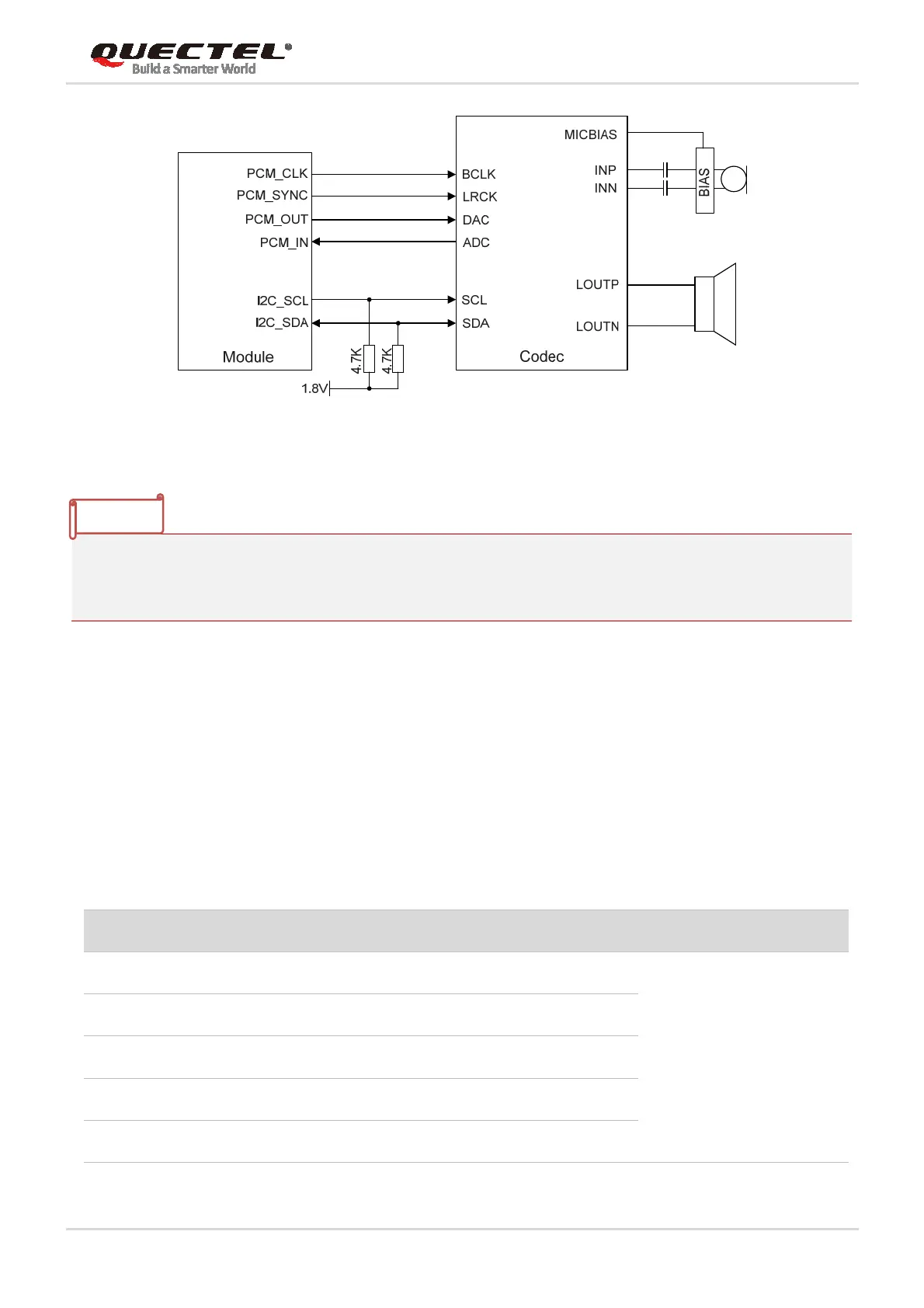
Figure 24: Reference Circuit of PCM Application with Audio Codec
1. It is recommended to reserve an RC (R=22Ω, C=22pF) circuits on the PCM lines, especially for
PCM_CLK.
2. EC25 works as a master device pertaining to I2C interface.
3.13. SD Card Interface
EC25 supports SDIO 3.0 interface for SD card.
The following table shows the pin definition of SD card interface.
Table 15: Pin Definition of SD Card Interface
Pin Name Pin No. I/O Description Comment
SDC2_DATA3 28 IO SD card SDIO bus DATA3
SDIO signal level can be
selected according to SD
card supported level,
please refer to SD 3.0
protocol for more details.
If unused, keep it open.
SDC2_DATA2 29 IO SD card SDIO bus DATA2
SDC2_DATA1 30 IO SD card SDIO bus DATA1
SDC2_DATA0 31 IO SD card SDIO bus DATA0
SDC2_CLK 32 DO SD card SDIO bus clock
NOTES