GNSS Module Series
LC29H_Series_EVB_User_Guide 14 / 38
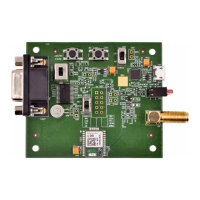
3.2. EVB Interfaces
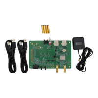
The EVB interfaces are detailed in the table below.
Table 3: Detailed EVB Interfaces
J201: Only used to supply power to avoid
the insufficient supply of J501.
J501: Used to communicate and supply
power.
Power supply input:
⚫ DC power supply: 4.5–5.5 V, typ. 5.0 V
⚫ Current capability should be > 100 mA
Supports standard NMEA message, RTCM
message, binary data, PAIR/PQTM
message and firmware upgrade.
Used for connecting GNSS antenna.
Used for testing 1PPS signal.
Bright: EVB is powered well.
Extinct: EVB is not powered.
Bright: Module is powered.
Extinct: Module is not powered.
Flashing: Successful position fix.
Frequency: 1 Hz.
Extinct: No position fix.
Flashing: Data are being output from UART
TXD pin.
Extinct or Bright: No data are output from
UART TXD pin.
Powers the module on/off.
Short press on the button to wake up the
module from Backup mode.
Short press on the button to reset the
module.
 Loading...
