EasyManua.ls Logo

Quectel RG500L EVB - Page 14

Quectel RG500L EVB
40 pages
Print Icon
To Next Page IconTo Next Page
To Previous Page IconTo Previous Page
Loading...
5G Module Series
RG500L_EVB_User_Guide 13 / 38
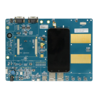
Table 2: Components & Interfaces of RG500L EVB
Interface
Reference
Designator
Description
Power Supply
J0201
The power jack on the EVB
Typical supply voltage: 12 V/ 3 A
Power Switch
S0203
VBAT ON/OFF control
PWRKEY
S1202
Power key (push button)
Used to turn on/off the module
USB_BOOT
S1205
Emergency download
PCIe Port Switch
S0401
Used to select PCIe port
RESET
S1204
Reset button (push button)
Used to reset the module
USB Interfaces
J1001
For AT command communication, data transmission
and firmware upgrade
J1303
For Linux console and log output
DSI_LCD
J0801
DSI LCD connector
DSI_TP
J0803
DSI TP connector
DBI_LCD
J0701
DBI LCD connector
DBI_TP
J0702
DBI TP connector
SLIC TE-A Interface
J1103
SLIC board TE-A connector
(U)SIM Card Interfaces
J0901
(U)SIM1 card connector
J0902
(U)SIM2 card connector
SD Card Interface
J0903
SD card connector
Module Status Indicators
D1205
Power supply on/off indicator, indicating whether the
module’s power supply is turned on or off
D1207
Module’s operation status indicator, indicating
whether the module is powered on
D1204
Network mode indicator, indicating whether the
module has registered on 5G network
D1208
Indicates the module’s network activity status
D1201
Indicates the VoIP function status
D1202
Indicates the (U)SIM card function status

Related product manuals