Figure 18: Reference Circuit with Translator Chip
Please visit http://www.ti.com for more information.
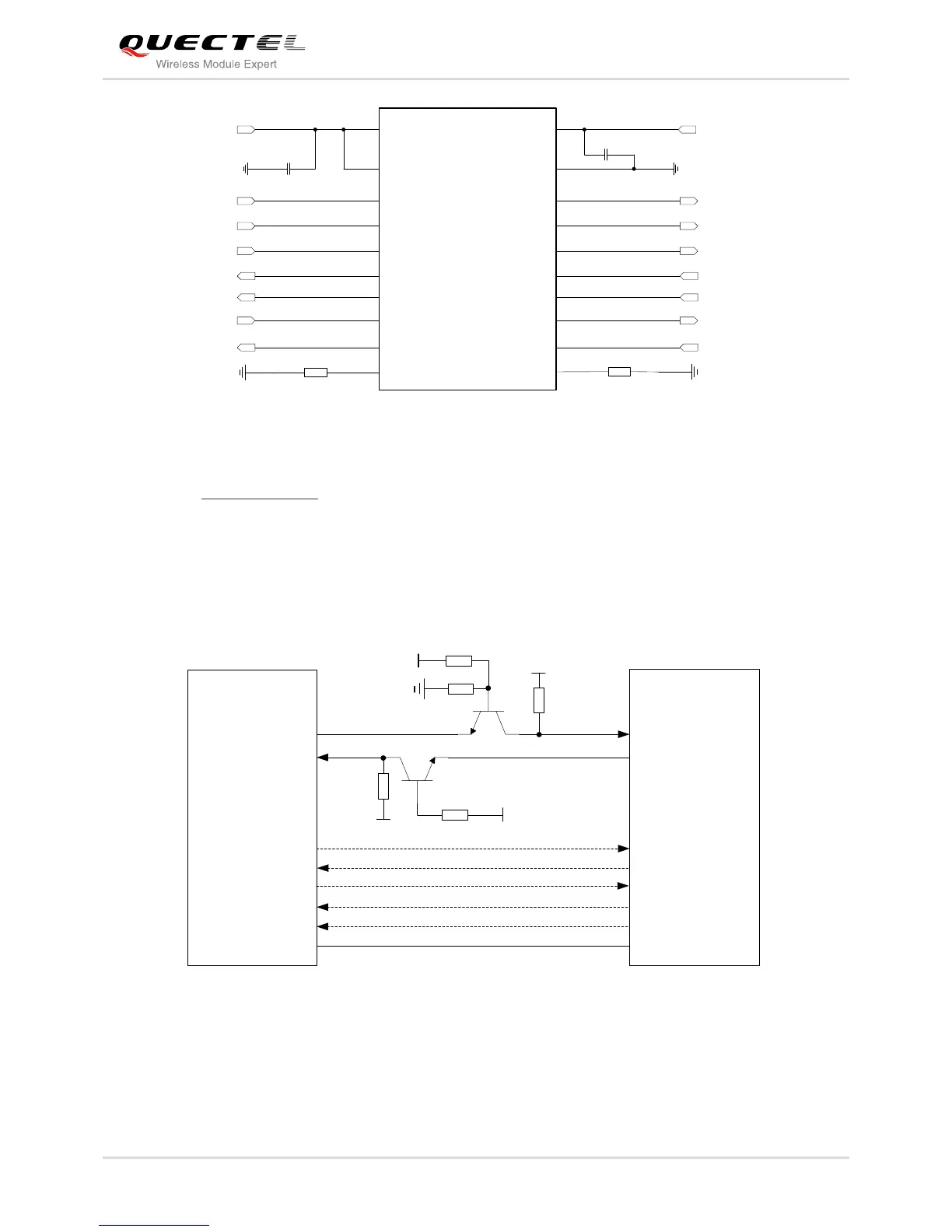
Another example with transistor translation circuit is shown as below. The construction of dotted line can
refer to the construction of solid line. Please pay attention to direction of connection. Input dotted line of
module should refer to input solid line of the module. Output dotted line of module should refer to output
solid line of the module.
Figure 19: Reference Circuit with Transistor Circuit
The following figure is an example of connection between UC20 and PC. A voltage level translator and a
RS-232 level translator chip must be inserted between module and PC, since these two UART interfaces
do not support the RS-232 level, while support the 1.8V CMOS level only.