UMTS/HSPA Module Series
UC20 Hardware Design
UC20_Hardware_Design Confidential / Released 42 / 84
3.11. USIM Card Interface
3.11.1. USIM Card Application
The USIM card interface circuitry meets ETSI and IMT-2000 SIM interface requirements. Both 1.8V and
3.0V USIM cards are supported.
Table 12: Pin Definition of the USIM Interface
Power supply for USIM card.
Either 1.8V or 3.0V is supported by
the module automatically.
Data signal of USIM card.
Pull-up to USIM_VDD with 15k
resistor internally.
Clock signal of USIM card.
Reset signal of USIM card.
USIM card insertion detection.
Specified ground for USIM card.
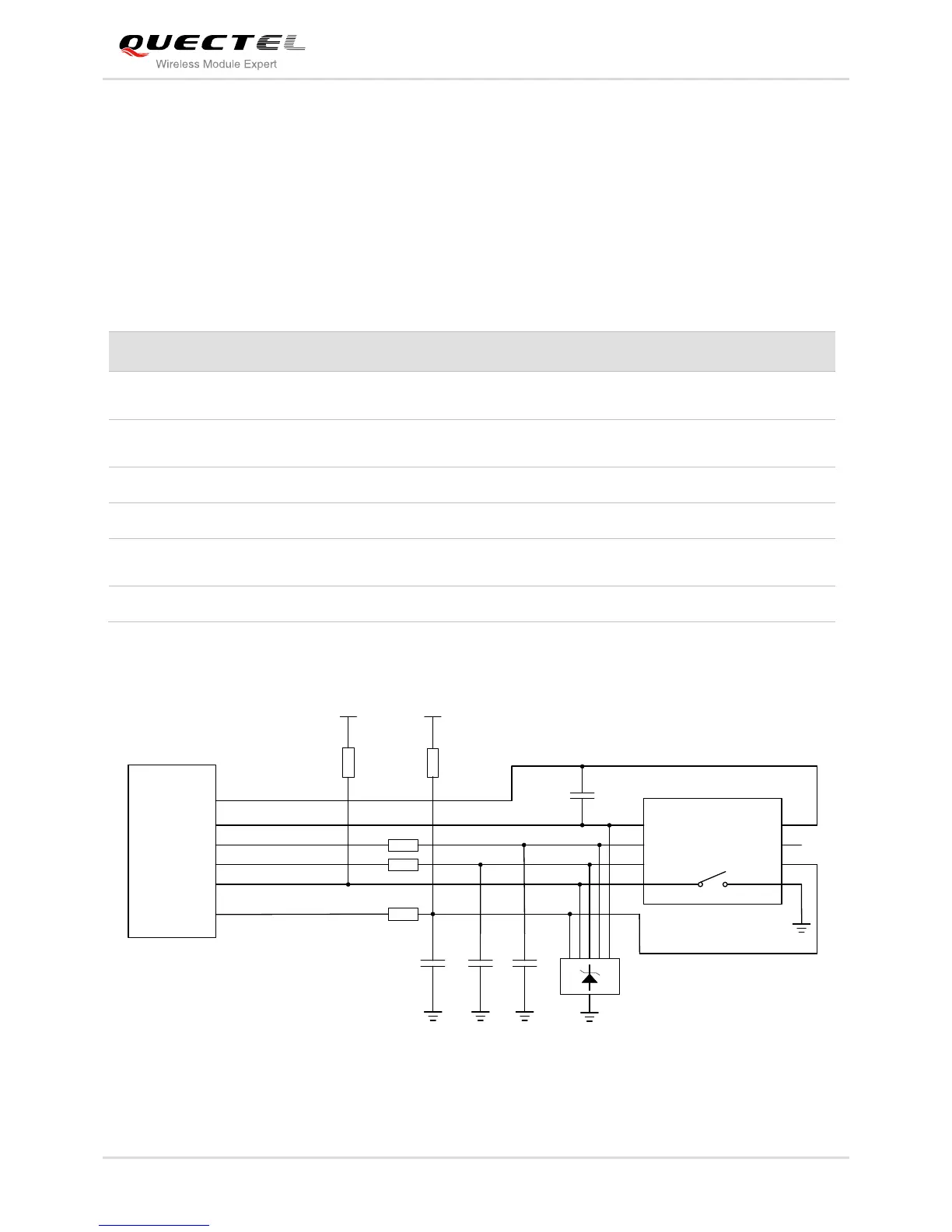
The following figure shows the reference design of the 8-pin USIM card.
Module
USIM_VDD
USIM_GND
USIM_RST
USIM_CLK
USIM_DATA
USIM_PRESENCE
22R
22R
22R
VDD_EXT
51K
100nF USIM Connector
GND
GND
ESDA6V8AV6
33pF
33pF 33pF
VCC
RST
CLK
IO
VPP
GND
GND
USIM_VDD
15K
Figure 22: Reference Circuit of the 8 Pin USIM Card