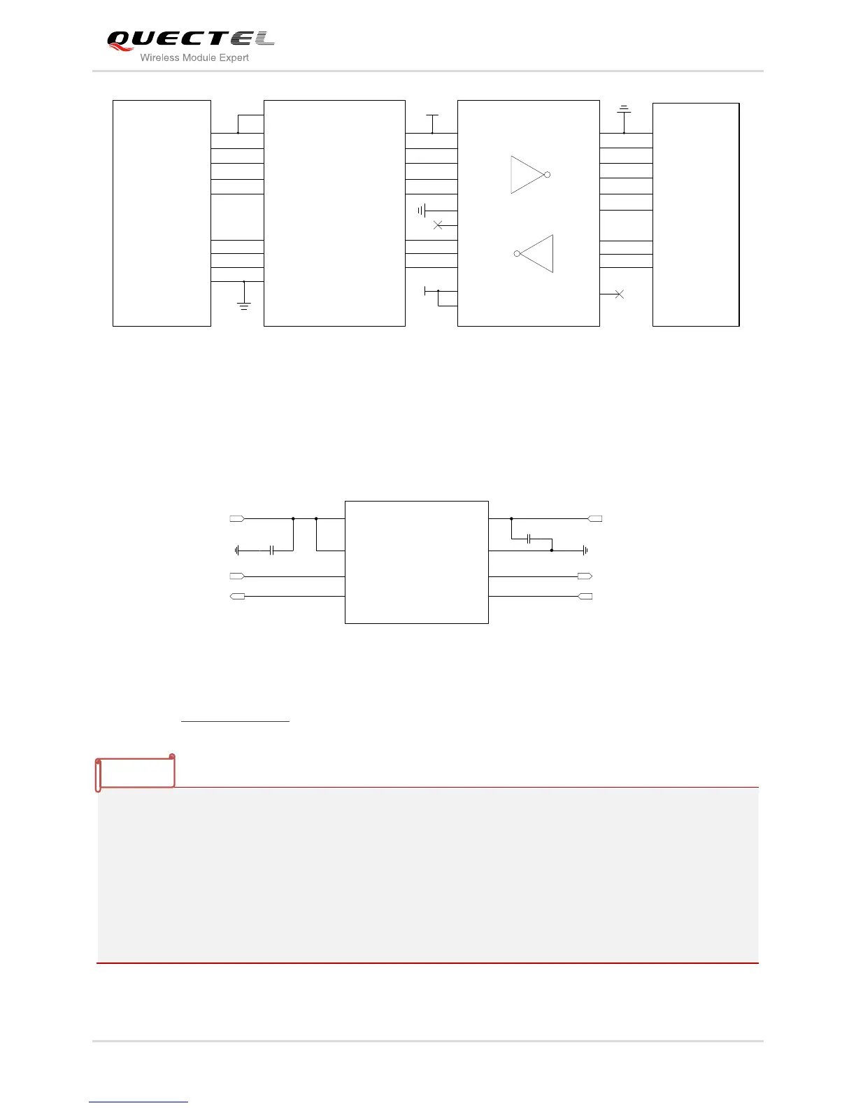
Figure 20: RS232 Level Match Circuit
The following figure shows the reference circuit of debug UART interface with logic level translator.
TXB0102DCU provided by Texas Instruments is recommended.
Figure 21: Reference Circuit of Debug UART with Level Translator
Please visit http://www.ti.com for more information.
1. The module disables the hardware flow control by default. When hardware flow control is required,
RTS and CTS should be connected to the host. AT command AT+IFC=2,2 is used to enable
hardware flow control. AT command AT+IFC=0,0 is used to disable the hardware flow control. For
more details, please refer to document [1].
2. Rising on DTR will let the module exit from the data mode by default. It can be disabled by AT
commands. Refer to document [1] about the command AT&D and AT&V for details.
3. DCD is used as data mode indication. Refer to document [1] about the command AT&C and AT&V
for details.