19
TCD 2022 / 2042
EN
INSTALLATION AND USE MANUAL - REV 002A
FUSE
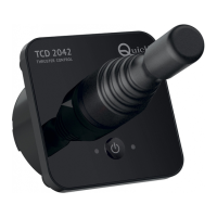
TCD 2042
THRUSTER
BAT TERY
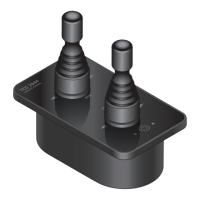
TCD 2022
RED
BLACK
RED
BLACK
MOTOR
SERVCE
BAT TERY
BAT TERY ISOLATOR
SWITCHFUSE
THRUSTER
(2)
(1) (1)
(2)
(3)
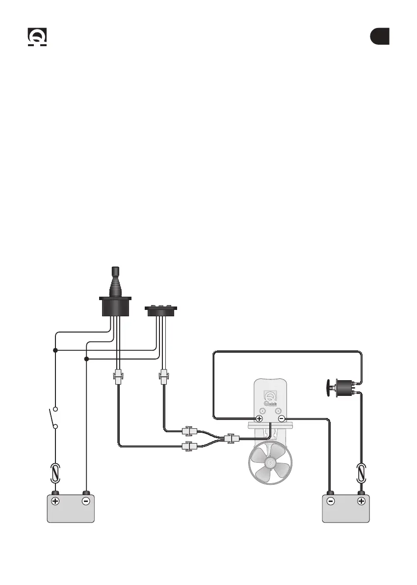
2.0 - INSTALLATION
(1) WARNING: COMMON NEGATIVE FOR THE BATTERY GROUPS
(2) EXTENSION CORD (OPTIONAL)
(3) SPLITTER (OPTIONAL)
Thruster basic system
2.3 - Electric connections
The control complies with EMC standards (electromagnetic compatibility) but requires correct installation to avoid
compromising its performance and that of the surronding instruments.
For this reason the interface wires must be positioned at a distance of at least:
• 1 m from cables that transmit radio signals (except for SSB radio transmitters).
• 2 m from cables for SSB radio transmitter signals.
Follow the rules below to construct the electrical installation relative to the control:
• Connect the control connector to the connector coming from the thruster.
• Fit a switch to turn the control on and off (not supplied).
• Position the switch so that it can be easily reached when the device must be turned off to prevent dangerous situations.
• Insert a 4A fast-blow fuse on the control power supply line (not supplied).
• Use cables with a cross-section appropriate for their lenght to supply the control.
• Do not use voltage from the motor or thruster battery groups to power the control.
• Check that all electrical connections are correct before powering the control.