GRB-200 Demodulator (GOES-R) OI&M
GRB-200 Demodulator (GOES-R) OI&M
© Copyright 2015, Quorum Communications, Inc.
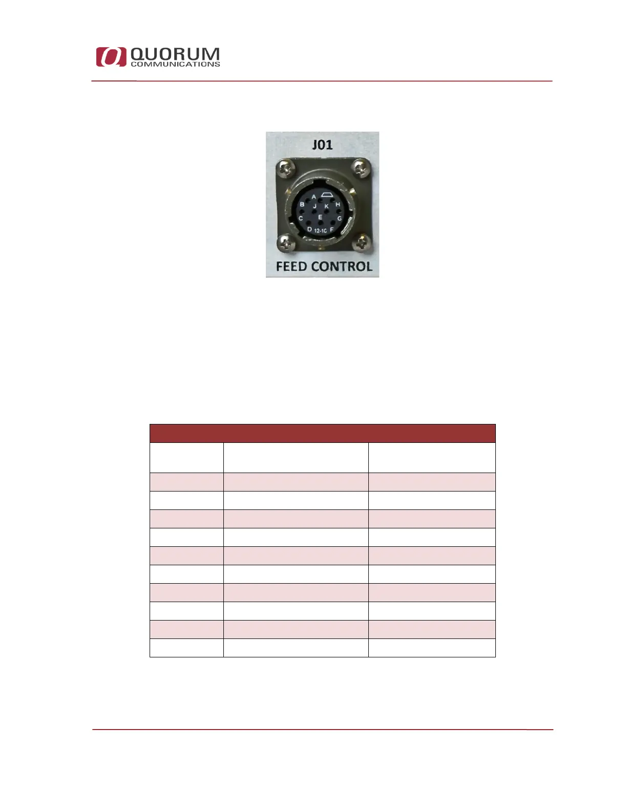
J01 Feed Control 2.3.2
Figure 8 – J01 Feed Control Connection
The Quorum GRB Reception Systems are provided with a pre-made
interconnect cable for the Quorum GRB Feed. Connect this cable between the
GRB Feed and the J1 Feed Control connector on the rear of the GRB
Demodulator.
J01 (PT06J-12-10S) Connection Pin-Out
Wire Color Purpose
GRB-200 Demodulator
(J01)Pin Letter
Red + 24 VDC A
Black Ground B
Yellow + 24 VDC C
Brown Ground D
Orange RS 485 + E
Violet RS 485 - F
Blue RSSI DCV G
Drain - Silver Case Ground H
Not Used J
Not Used K
Table 2 - J01 Connection Pin Out