GRB-200 Demodulator (GOES-R) OI&M
GRB-200 Demodulator (GOES-R) OI&M
© Copyright 2015, Quorum Communications, Inc.
SECTION 3 OPERATING INSTRUCTIONS
3.1 CONTROLS AND INDICATORS
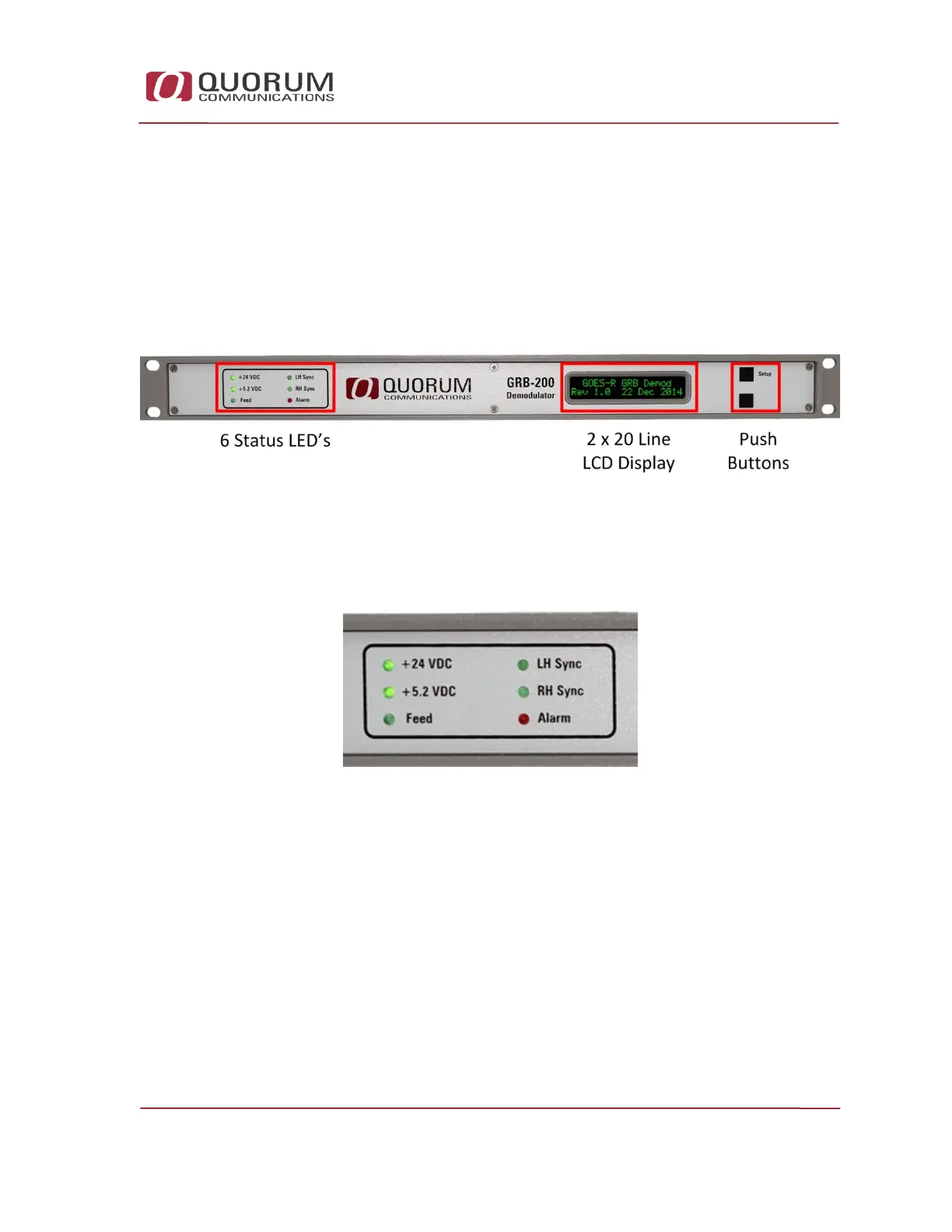
The GRB front panel has a 2 line by 20 character LCD display used for basic
status, diagnostic and configuration data display, 6 individual LED’s to indicate
important status and 2 push button switches which are used to change the
information displayed and configure the demodulator operation.
Figure 13 - GRB-200 Demodulator Controls and Indicators
Status LED’s 3.1.1
Six status LEDs are grouped on the left side of the front panel.
Figure 14 - Status LED's
+24 VDC: 24 volts is present from the power supply
+5.2 VDC: 5.2 volts is present from the power supply
Feed: the demodulator is receiving status data from the connected GRB feed
LH Sync: the demodulator is receiving DVB-S2 baseband frames on the LHCP
input
RH Sync: the demodulator is receiving DVB-S2 baseband frames on the
RHCP input
Alarm: an alarm condition is present. The alarm will be displayed on the LCD
display and inserted into the UDP status message.