© 2014 Radiodetection Ltd 30
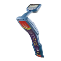
Figure 8.7 Sonde deployment
To locate a sonde:
1 Move the locator backwards and forwards and
stop when the bar graph indicates a peak. You
can use the LCD compass to orient the blade of
the locator with the direction of the sonde.
2 Rotate the locator as if the blade is a pivot. Stop
when the bar graph indicates a peak.
Figure 8.7 Locating a sonde
3 Move the locator from side to side until the bar
graph indicates a peak.
4 Repeat 1, 2 and 3 with the antenna vertical and
resting on or just above the ground. The locator
should then be directly above the sonde with the
antenna in line with it. Mark the position of the
sonde and its direction.
5 Propel the sonde a further 1 or 2 meters,
pinpoint, and mark the position. Repeat this
pinpoint procedure at similar intervals along the
line of the drain or duct until the survey is
completed.
8.5.6 Checking sonde depth
The RD7000+ locator will automatically display the
depth of a located sonde providing the locator is
correctly oriented and positioned above the sonde.
Using the LCD compass as a guide, rotate the locator
until the compass indicates the sonde is in East/West
position.
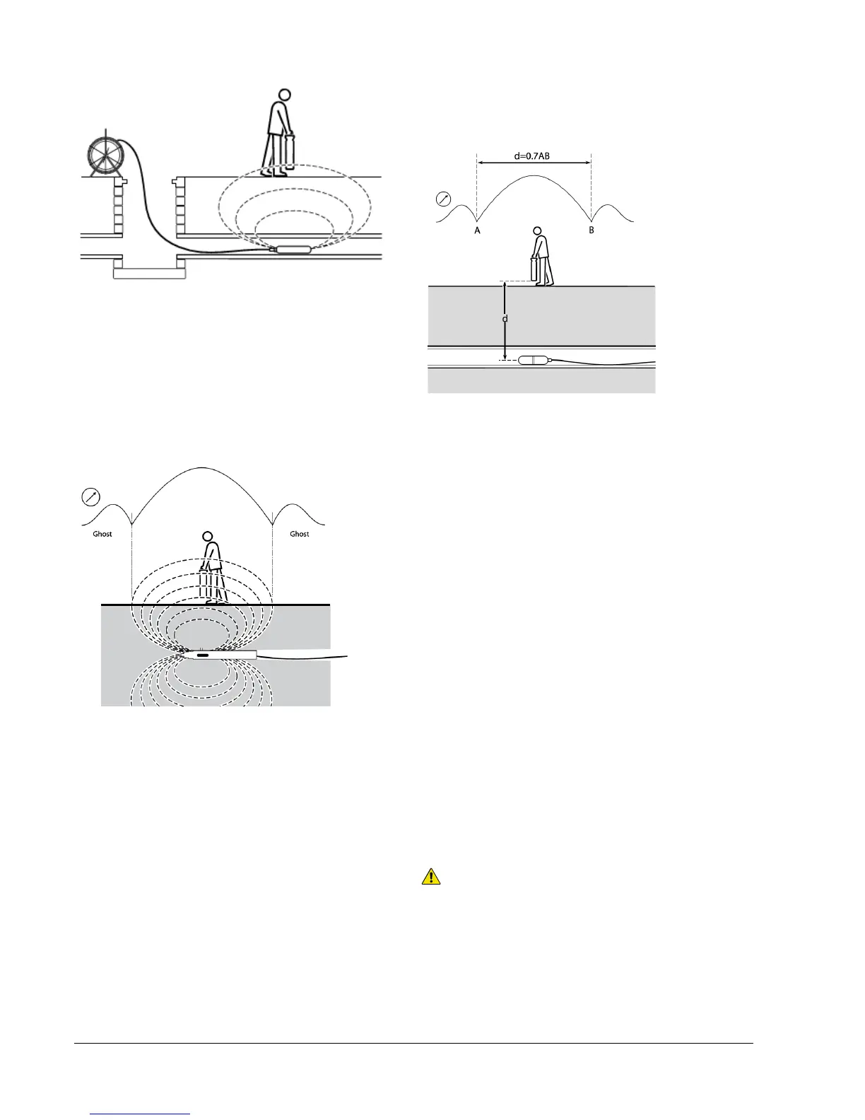
Figure 8.9: Calculating sonde depth
Calculation method
Pinpoint the sonde. Move the locator in front of the
sonde and still with the antenna in line with it, increase
sensitivity to find the peak of the ghost signal. Move the
locator to behind the sonde ensuring that the locator
blade is always in line with the sonde. Find the null
positions A and B (See Figure 8.9 ). Measure the
distance between them and multiply by 0.7 to give an
approximate depth measurement.
8.5.7 FlexiTrace
The FlexiTrace is a traceable plastic covered fiberglass
rod incorporating wire conductors and is used for
locating small diameter, non-metallic pipes to a depth of
3 meters. The FlexiTrace can be inserted into a pipe or
duct as small as 12 mm/0.5 inch internal diameter with a
minimum bend radius of 250mm. Batteries are not
required, as the FlexiTrace is powered by the RD7000+
Marker transmitter.
The FlexiTrace has a maximum power rating of 1W.
When using the FlexiTrace with a Radiodetection Tx-5
or Tx-10 transmitter the output limit must be set to 1W in
the MAX P menu and the output voltage limit set to
LOW in the MAX V menu.
No settings are required for the Tx-1 transmitter.
WARNING: Failure to follow the Tx-5 or Tx-10
instructions above may result in the tip of the FlexiTrace
becoming too hot to touch, resulting in risk of personal
injury and damage to the equipment.
The FlexiTrace can be used in two modes: Sonde mode
or Line mode. In sonde mode only the tip of the
FlexiTrace is energized whilst in line mode its whole
length is energized.