© 2014 Radiodetection Ltd 14
When eco mode is active and the power output has
been reduced, the display flashes between POWER
and the current output power level.
The transmitter will emit three beeps every time the
power is reduced. It will then continue emitting two
beeps every minute whilst it operates at a reduced
power level.
To enable Eco mode
1 Press the key to enter the menu
2 Scroll to the BATT menu using the or keys
and enter it by pressing the key.
3 Scroll up or down to the ALK menu and enter it by
pressing the key.
4 Select ECO and press the key to enable the
Eco mode option
Or
Select NORM and press the key to disable Eco
mode.
5 Press the key to exit the menu
3.14 Measure mode
The transmitter has the capability of providing
impedance measurements by determining the resultant
impedance across the crocodile clips of the direct
connection lead while connected to the utility. These
measurements can be useful when assessing sheath
fault severity. It is also possible to measure potential
voltage that may be present on utilities to warn of
potentially dangerous or harmful voltages present.
In measure mode the measurement is derived from an
AC signal applied to the utility from the transmitter.
3.14.1 Impedance and voltage
measurements
1. Connect the direct connection leads to the utility
and switch on the transmitter.
2. Hold down the key until MEAS is displayed
and the measuring icon is activated.
The transmitter display will now indicate the
voltage level measured across the connection
leads.
3. Press the key once and the display will
indicate the impedance measured across the
connection leads.
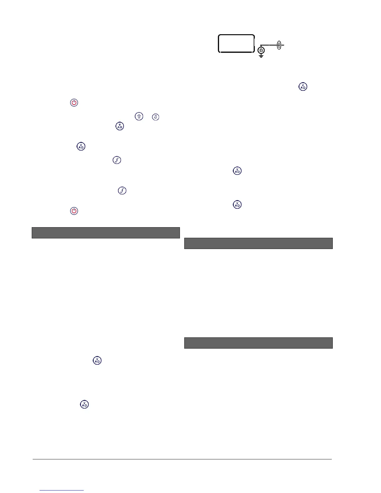
The measurement icon will display the following
symbols:
Figure 3.8 Impedance and voltage measurements
4. To exit MEAS mode hold down the key until
the display reverts back to the normal operating
screen.
3.14.2 Impedance measurements
using active frequency
1. Connect the direct connection lead to the utility
and switch on the transmitter.
2. Select the preferred frequency and output the
signal.
3. Press the key once and the display will
indicate the impedance measured across the
connection leads and also the output power of
the transmitter.
4. Press the key once to return to the normal
operating screen.
3.15 CALSafe
CALSafe enabled RD7000+ logging locator models are
equipped with a system which disables them once they
are past the expected service/calibration date.
When the unit is within 30 days from the service due
date the unit will display at startup the number of days
left. The locator will stop functioning on the service due
date.
You can edit the CALSafe service due date or disable
this function using the RD Manager PC software. Refer
to its operation manual for further information.
3.16 Automatic Logging
RD7000+PLM and TLM locator models offer a powerful
data logging system which records all the instrument’s
critical parameters and warnings in its internal memory
every second.
The automatic logging system is always active and
cannot be disabled. Its memory is capable of storing at
least 1 years’ worth of normal usage data – based on 4
hours operation per day, 5 days per week and 20 days
per month.
Logs can be retrieved using the RD Manager PC
application for usage analysis and survey validation.
Refer to its operation manual for further information.