© 2014 Radiodetection Ltd 4
Section 2 - System overview
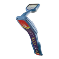
2.1 RD7000+ marker locator
2.1.1 Locator features
1 Keypad
2 LCD with auto backlight
3 Speaker
4 Battery compartment
5 Battery charger socket
6 Accessory socket
7 Headphone socket
8 Bluetooth module antenna
9 Marker loop antenna
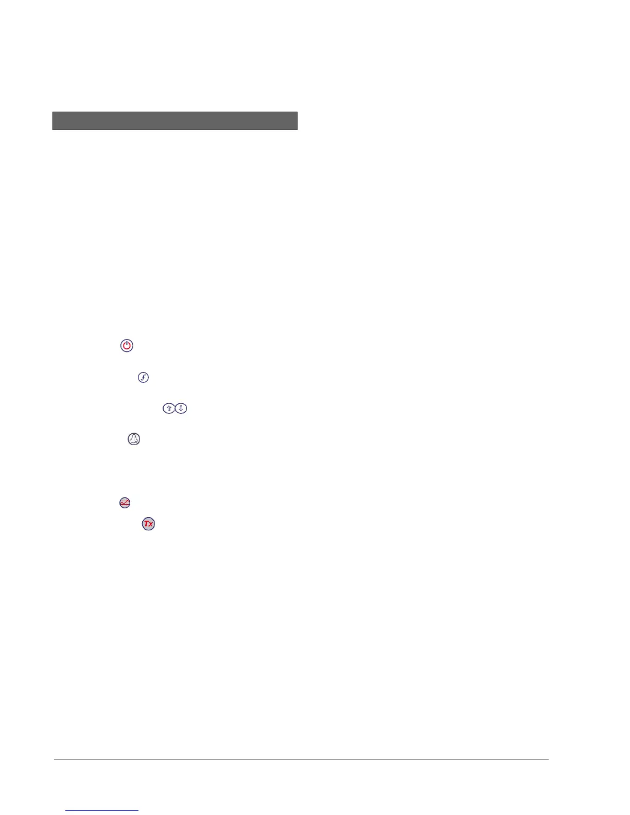
2.1.2 Locator keypad
10 Power key : Switches the unit on and off. Opens
the locator menu
11 Frequency key : Selects frequency. Closes
submenu
12 Up and down arrows : Adjusts the signal gain.
Scrolls through the menu options
13 Antenna key : With antenna folded up, toggles
peak, combined peak/null and null (PL and TL
models) modes. With antenna folded down, toggles
marker and combined (marker/line) modes. Opens
a submenu
14 Graph key : Send Survey measurements
15 Transmitter key : Not used
2.1.3 Locator screen icons
16 Indicates the signal strength and peak marker.
17 Signal strength: Numerical indication of signal
strength
18 Peak / Proportional arrows: Indicates the location of
the line relative to the locator
19 Battery icon: Indicates the battery level
20 Volume icon: Displays the volume level
21 Fault-Find arrows (PL and TL models only).
22 Radio Mode: Indicates when Radio Mode is active
23 Power Mode: Indicates when Power Mode is active
24 Accessory indicator: Indicates when an accessory is
connected
25 A-Frame icon: Indicates when the A-Frame is
connected
26 Operating mode indicator
27 Bluetooth icon: Indicates status of Bluetooth
connection. Flashing icon means pairing is in
progress. Solid icon indicates an established
connection is active
28 Antenna mode icon: Indicates antenna selection:
Peak, Null and combined Peak/Null.
29 Sonde icon: Indicates that the signal source is from
a sonde (DL, PL and TL models).
30 Line icon: Indicates that the signal source is from a
line.
31 Compass/Marker mode indicator: Shows the
direction of the located cable relative to the locator.
Also used as a graphical indication for Marker mode
active
32 Current / depth indicator