Radiolink Electronic Ltd
www.radiolink.com
5.2.3 Connect the Spare Parts
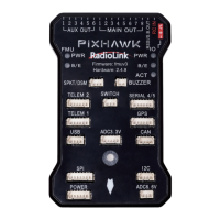
Buzzer: a 2-pin DF13 connector to the BUZZER port
Safety switch: a 3-pin DF13 connector to the SWITCH port .
Power Module: a 6-pin DF13 connector to the POWER port
GPS and compass: a 6-pin DF13 connector to the GPS port( eg. TS100) or a 4-pin DF13 connector to the
I2C port (Make sure that GPS keeps the same direction as PIXHAWK).
5.2.4 Battery Monitors Setup
The battery monitor module provides a stable 5.37V and 2.25Amp power supply which reduces the chances
of a brown-out.
Allows monitoring of the battery’s voltage and current and triggering a return-to-launch when the voltage
becomes low or the total power consumed during the flight approaches the battery’s capacity.
Allows the autopilot firmware to more accurately compensate for the interference on the compass from other
components.
The 6-pin cable plugs into the 6-pin connector on both the Power Module and PIXHAWK.

 Loading...