RadioLink Electronic Ltd
www.radiolink.com
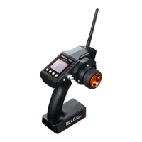
2.22 Subsidiary ID “ID SEED”
ID SEED function means designating a subsidiary ID among multiple binding receivers to realize the control.
There are totally 10 independent subsidiary IDs can be stored. The four numbers displayed at the bottom of
the screen are the independent ID codes of this transmitter.
For example, RC6GS V3 has completed the binding with 10 different boats and the setup of respective
parameters. Turn on the ID SEED function, select ID.1 boat and drive it to the central of water but it stops
working unexpectedly. Then we can change to the ID.2 boat (or any other subsidiary ID boat preferred) and
control it independently to rescue ID. 1 boat instead of controlling both boats at the same time, which makes
the rescue more difficult. Unlike traditional binding mode, independent ID can easily realize rescuing stalled
boat in the water caused by various reasons.
Press EXIT and ENTER simultaneously to enter MENU=>press Inc(+)/DEC ( - ) to highlight “22. ID
SEED=>Press ENTER => Change the MODE from OFF to ON=> set the subsidiary ID number=> complete
biding and parameters setting.
Once finished , the corresponding ID number will be displayed on the RC6GS V3 main interface .
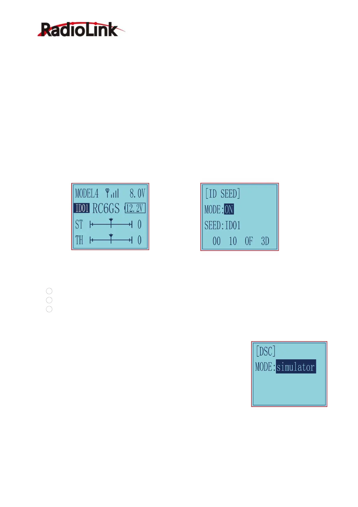
2.23 DSC port setting “DSC”
There are 3 modes for DSC function.
1 Simulator: Connect to the simulator or TBS Crossfire;
2 2 axis track: Connect to FPV goggles with head track function.
3 3 axis track: Connect to FPV goggles with head track function. (RC6GS V3 with firmware V6.7.7 or
above supports 3 axis track. If the firmware version is lower than V6.7.7, please update the firmware to use
the 3 axis track function)
Simulator mode: If you need to connect simulator or TBS Crossfire to the DSC
port of RC6GS V3, please select the mode as: simulator. When connecting the
simulator, insert one end of the standard audio head of the simulator into the
DSC port of RC6GS V3, and follow the steps in the simulator instruction manual
to calibrate and operate the transmitter in the simulation software. The following
picture is for reference. (Please refer to the video for the method of connecting
RC6GS V3 to TBS Crossfire:
https://www.youtube.com/watch?v=6vt5QexQSQs

 Loading...