Raisecom
RC3000E (P100R001) Product Description
Raisecom Proprietary and Confidential
Copyright © Raisecom Technology Co., Ltd.
other card in later slot occupies the main channel, channel collision alarm will be
reported. The range for the card in slot 3 is 0–15. 0 refers to disabling
transmission of this card and the channel starts from 17.
Limitations for independent channel configurations: When you use the
independent channel to transmit data, the range is 0–31. There will not be any
channel collision alarm and the channel No. starts from 1.
4.8.2 Slots
The RC3000-SUB-DV35 can be inserted into slots 1–3. For the used cable, see section 7.2.5
CBL-VOICE-SCSI50M(40)/NC.
4.8.3 Interfaces
Receive Data (A) (RD (A))
Receive Data (B) (RD (B))
Receive Timing (A) (RCK (A))
Receive Timing (B) (RCK (B))
Send Timing (A) (TCK (A))
Send Timing (B) (TCK (B))
Terminal Timing (A) (SCTE (A))
Terminal Timing (B) (SCTE (B))
Data Carrier Detect (DCD)
Data Terminal Ready (DTR)
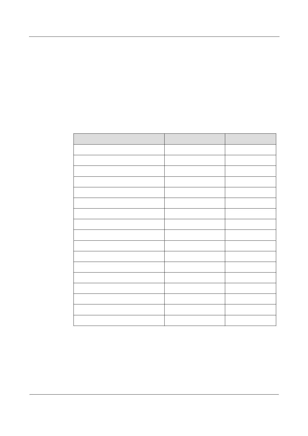
4.8.4 LEDs
Table 4-7 lists the LEDs on the RC3000-SUB-DV35.