EasyManua.ls Logo

Raisecom RC3000E - Figure 4-5 Appearance of the RJ45 Interface; Table 4-8 Relationship between the Channel and the PIN; Table 4-9 Definitions of the DB25 Signal

Raisecom RC3000E
91 pages
Print Icon
To Next Page IconTo Next Page
To Previous Page IconTo Previous Page
Loading...
Raisecom
RC3000E (P100R001) Product Description
4 Cards
Raisecom Proprietary and Confidential
Copyright © Raisecom Technology Co., Ltd.
37
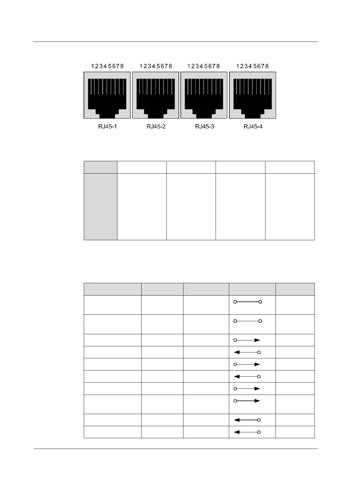
Figure 4-5 Appearance of the RJ45 interface
Table 4-8 lists the relationship between the channel and PIN
Table 4-8 Relationship between the channel and the PIN
Channel
1
2
3
4
PIN
RJ45-1
2 RDATA
3 TDATA
6 RCLK
7 TCLK
1, 4, 5, and 8
GND
RJ45-2
2 RDATA
3 TDATA
6 RCLK
7 TCLK
1, 4, 5, and 8
GND
RJ45-3
2 RDATA
3 TDATA
6 RCLK
7 TCLK
1, 4, 5, and 8
GND
RJ45-4
2 RDATA
3 TDATA
6 RCLK
7 TCLK
1, 4, 5, and 8
GND
Table 4-9 lists the definitions of the DB25 signal.
Table 4-9 Definitions of the DB25 signal
Function
Mnemonic
PIN
InOut
Remarks
Frame Ground
(FGND)
101/FGND
1
Signal Ground
(SGND)
102/SGND
7
Transmit Data (TD)
103/TD
2
Receive Data (RD)
104/RD
3
RTS
105/RTS
4
ON
CTS
106/CTS
5
DTR
108/DTR
20
ON
Terminal TX Clock
(TTC)
113/TTC
24
Idle
TX Clock (TC)
114/TC
15
Idle
RX Clock (RC)
115/RC
17
Idle

Table of Contents

Related product manuals