EasyManuals Logo

Raisecom RC3000E User Manual

Raisecom RC3000E
91 pages
To Next Page IconTo Next Page
To Previous Page IconTo Previous Page
Page #54 background imageLoading...
Page #54 background image
Raisecom
RC3000E (P100R001) Product Description
4 Cards
Raisecom Proprietary and Confidential
Copyright © Raisecom Technology Co., Ltd.
43
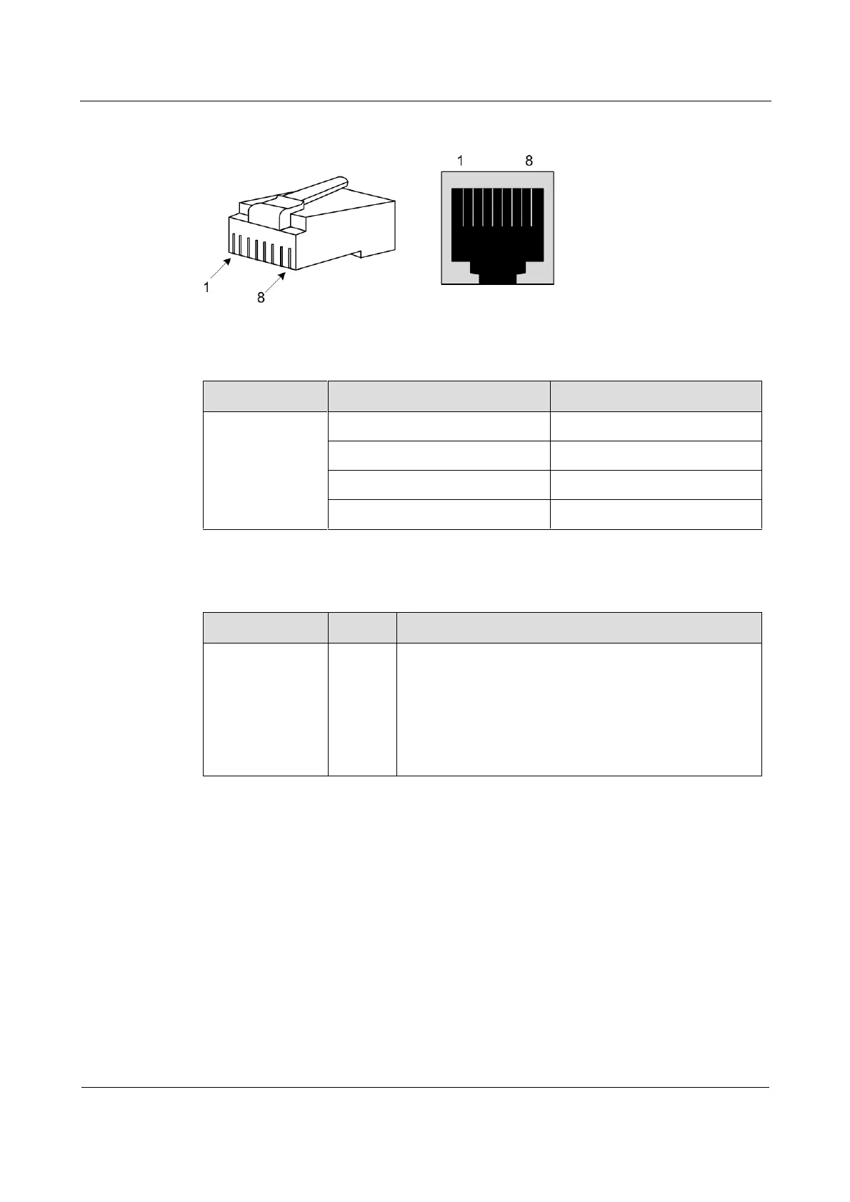
Figure 4-8 PIN definitions of the RJ45 interface on the RC3000-SUB-DMT (B.00)
Table 4-17 lists the mapping between the channel and PIN.
Table 4-17 Mapping between the channel and PIN
RJ45
PIN
Channel
RJ45-1
1 T and 2 R
1
3 T and 4 R
2
5 T and 6 R
3
7 T and 8 R
4
4.12.4 LEDs
LED
Status
Description
IN_USE
Green
Voice channel in-use LED, indicating 2100 Hz signaling
status in magneto mode (enabled with 2100 Hz signaling)
or digital signaling status in common mode (disabled with
2100 Hz signaling)
Green: the voice channel is receiving or sending
signaling.
Off: the voice channel is idle.
4.12.5 Technical specifications
Dimensions: 70 mm (Width) × 167.5 mm (Depth) × 20 mm (Height)

Table of Contents

Questions and Answers:

Question and Answer IconNeed help?

Do you have a question about the Raisecom RC3000E and is the answer not in the manual?

Raisecom RC3000E Specifications

General IconGeneral
BrandRaisecom
ModelRC3000E
CategoryMultiplexer
LanguageEnglish

Related product manuals