CHAPTER 2
10 Hawkeye® 2 Installation Manual for AGCO RoGator C-Series (RG900, RG1100, RG1300)
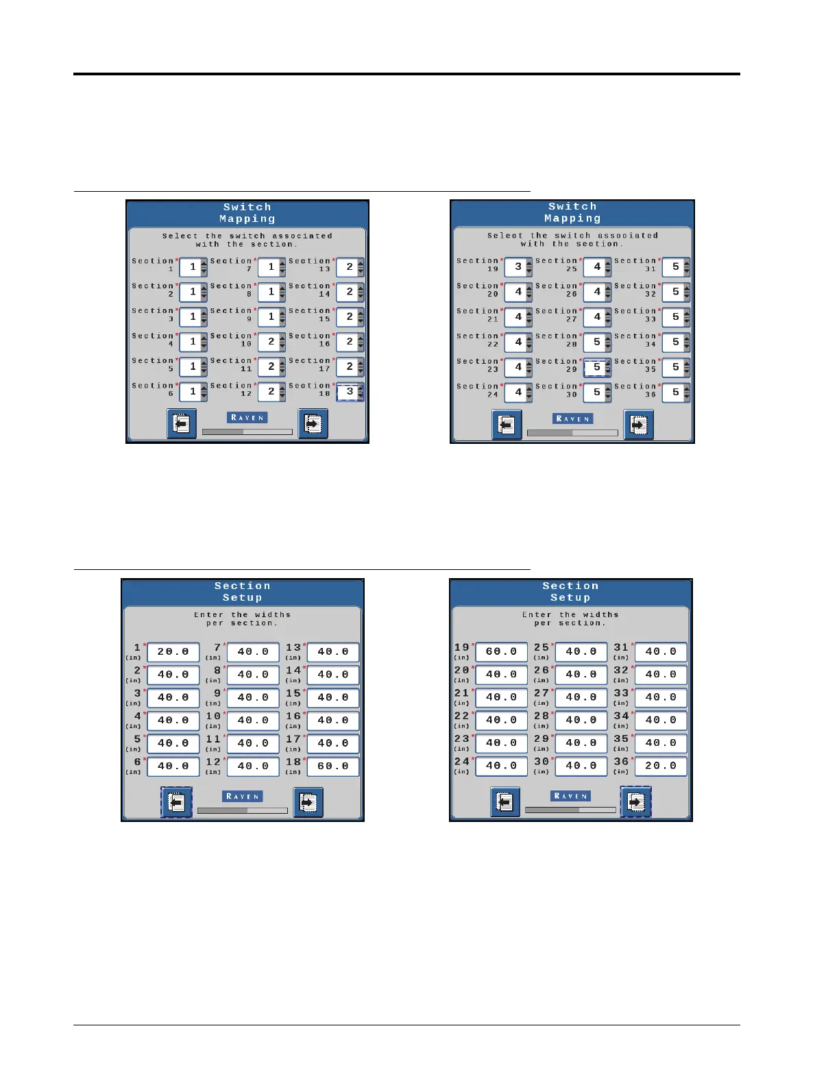
4. For each section, use the color coordination in the tables above to select which switch the section will be
mapped to as shown in Figure 2, “Switch Mapping - Assigning Sections,” below.
NOTE: Only use numbers 1-5 in the drop-down list for each section according to the color code in the tables.
FIGURE 2. Switch Mapping - Assigning Sections
NOTE: Number of switches may vary from the images shown above.
5. Ensure that the displayed values match the table, and then press Next.
6. For each section, enter the corresponding section width value from the tables above as shown in Figure 3,
“Section Setup - Section Widths,” below.
FIGURE 3. Section Setup - Section Widths
NOTE: Number of sections may vary from the images shown above.
7. Ensure the displayed selections are accurate, and then press Next.
NOTE: When using a standard Hawkeye® 2 kit coupled with Pro-stop E, create two profiles: one profile with
16 virtual sections for Hawkeye® 2 nodes, and a second profile with 36 sections of Pro-stop E for
Bypass mode. When creating Bypass profile, skip indexing in order to configure the 36 sections.
Hawkeye® 2 Premium with HD control will only require one setup of 36 sections.
 Loading...