6
Chassis Cable Installation: Hawkeye® 2 Power Connections (No Injection) 45
CHASSIS CABLE INSTALLATION
HAWKEYE® 2 POWER CONNECTIONS (NO INJECTION)
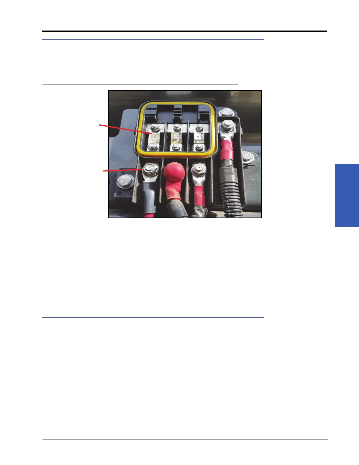
1. Locate the three way fuse panel under the right-rear of the catwalk.
2. Place an 70 Amp AMI fuse (P/N 510-1003-048) in one of the two rear positions of the fuse panel.
FIGURE 3. Hawkeye® 2 Power Connection (No Injection)
NOTE: If the system will include Sidekick Pro™ ICD injection, a secondary fuse panel is required. The injection
pumps and Hawkeye® 2 will be powered via the secondary fuse panel. Refer to “Sidekick Pro™ ICD
Installation” section on page 49 for additional information.
3. Connect one the M8 x 1.25 output studs to the power supply.
4. Route the ground wire along the frame rail and then behind the cab, across to the right side of the sprayer.
5. Remove the battery box cover on the catwalk floor, outside of the cab door.
6. Route the ground wire into the battery box and connect to the ground lug of the battery.
7. Replace the battery box cover and secure the ground cable with zip ties.
SYSTEM DIAGRAMS
Diagrams start on the next page.
AMI Fuse
Power
Connections
 Loading...