4
Nozzle Body and Nozzle Control Valve Installation: Hawkeye® 2 Nozzle Body Installation 25
NOZZLE BODY AND NOZZLE CONTROL VALVE INSTALLATION
AGCO SPRAY BOOMS NOZZLE BODY ASSEMBLY
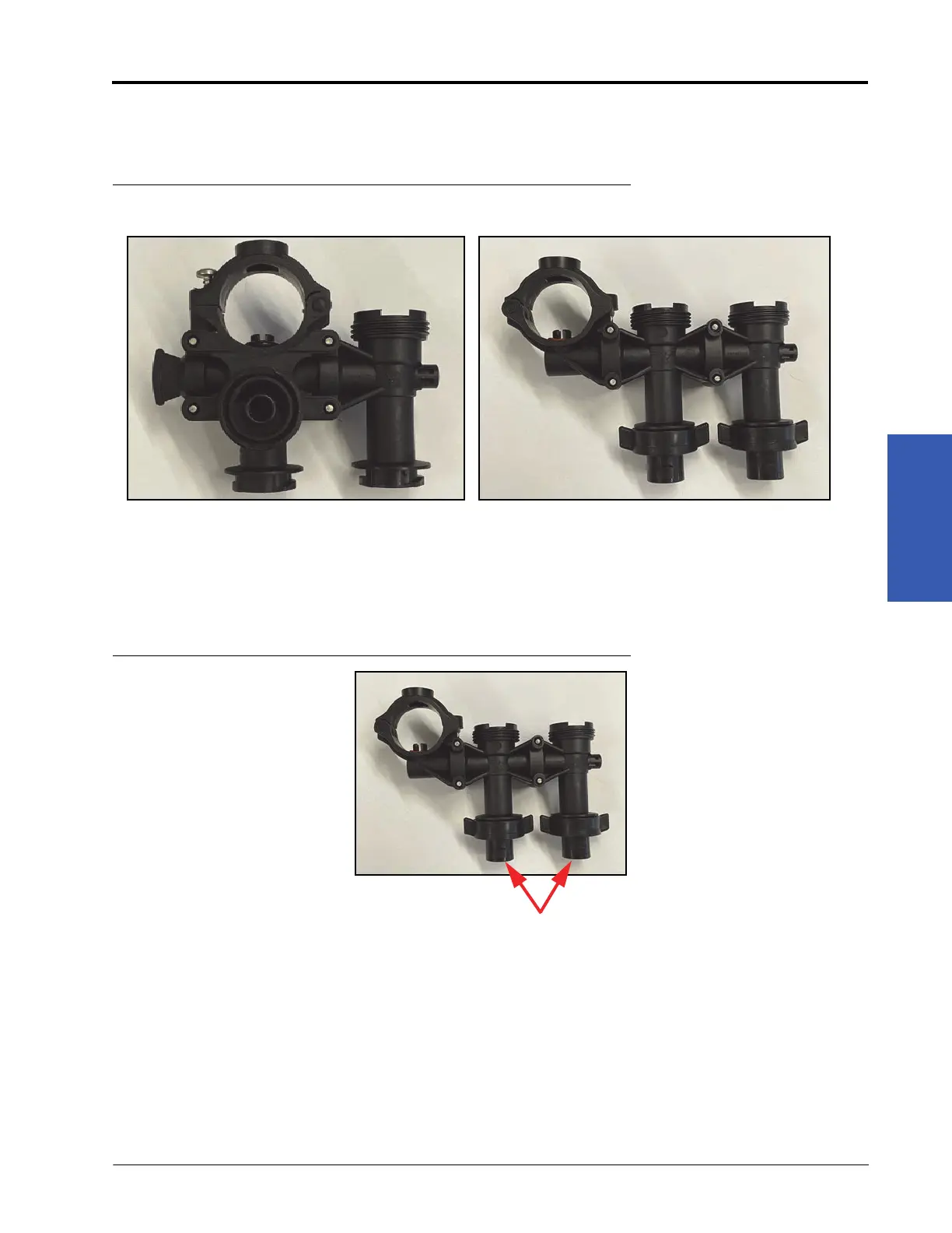
1. Locate the components provided to assemble the two configurations of the nozzle bodies.
FIGURE 3. Wilger Nozzle Body Configurations
2. Remove the stainless steel U-clip provided with the nozzle bodies.
3. Align the nozzle body or plug as necessary and reinstall the U-clip to secure.
4. If the Wilger-to-Square lug tip adapters are needed to accommodate the tips to be used, install them on the
outlets of the nozzle bodies by rotating them a quarter turn.
FIGURE 4. Outlets of the Nozzle Body
Center Section
of Machine
Boom Wings
A
B
Square Lug Tip
Adapters Installed
 Loading...