4
FIGURE 2
FIGURE 3FIGURE 1
INSTALLATION
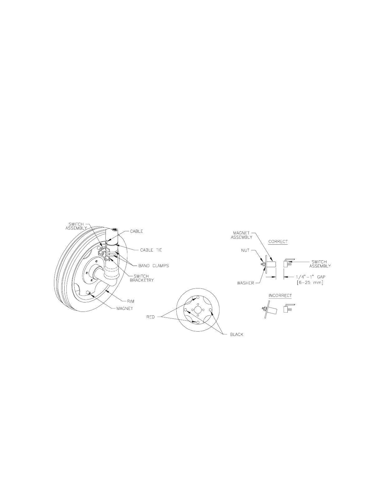
1. MOUNTING WHEEL DRIVE SPEED SENSOR
The Wheel Drive Speed Sensor consists of four magnets, a switch assembly with
cable, and mounting hardware. (Installation instructions for the optional Radar
Interface Speed Sensor are included in their shipping carton. See Appendix 7 for
the installation instructions for Wheel Drive Speed Sensor with six magnets).
Sequence of mounting Speed Sensor:
l) Select a non-driven wheel (left front tractor wheel or implement wheel).
2) Check for predrilled holes in rim. If not predrilled, see Appendix 1.
3) Mount the four magnets to inside of rim and tighten. (See Figures 1, 2, & 3).
Magnets must be mounted in alternating red-black order.
4) Mount switch assembly to stationary column with the hardware provided. (See
Figure 1). The switch assembly need not pivot with the wheel.
5) Position switch assembly so that as the wheel rotates the magnets pass across
the center of the black, molded switch assembly. (See Figures 1 & 3).
6) Clearance gap between magnets and switch assembly must be between 1/4 inch
[6 mm] and 1 inch [25 mm]. With wheels pointed straight ahead, rotate wheel to
ensure gap is correct. Make sure vehicle wheels can be turned to their extremes
in each direction without the magnets hitting the switch assembly.
7) Tighten switch assembly bracketry.
8) Secure cable to column with plastic cable ties.
 Loading...