7
INSTALLATION
1. MOUNTING THE FLOW METER AND OPTIONAL
PRESSURE TRANSDUCER
(LIQUID APPLICATIONS)
FLOWMETER
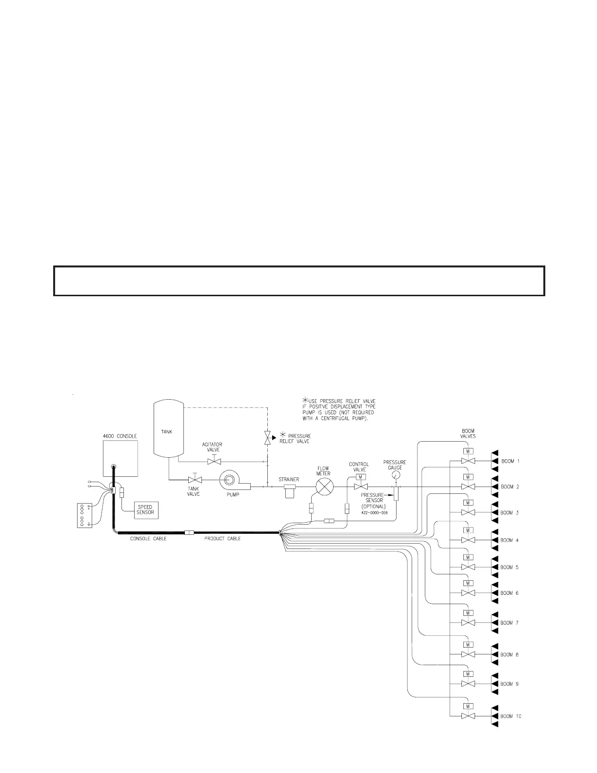
1) Mount Flow Meter in the area of the boom valves per Figure 1. All flow through Flow Meter must go
to booms only, i.e., no return line to tank or pump after Flow Meter.
2) Mount Flow Meter horizontal to the ground. Use the bracket to secure the Flow Meter.
3) For best results, allow a minimum of 7 1/2 inches [20 cm] of straight hose on inlet of Flow Meter.
Bend radius of hose on outlet of Flow Meter should be gradual.
4) Flow must be in direction of arrow on Flow Meter.
FIGURE 1
LIQUID SYSTEM DIAGRAM
NOTE: It is essential, when using suspensions, that the system be thoroughly rinsed out
each day after use.
OPTIONAL PRESSURE TRANSDUCER
1) Mount optional pressure transducer, Raven P/N 422-0000-059, on desired location. Use appropri-
ate cabling.
2) With pump turned off and 0 PSI [kPa] on the lines, enter 0 for pressure calibration (ENTER PSI[KPA])
under Data Menu Key.

 Loading...