nVent.com | 9
2.5 WIRING
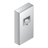
The following drawings provide sample wiring diagrams for the C910-485 control products
and optional accessories. Refer to Figure 2.2 for wiring terminal locations. Please contact
your local nVent representative for information regarding other available options.
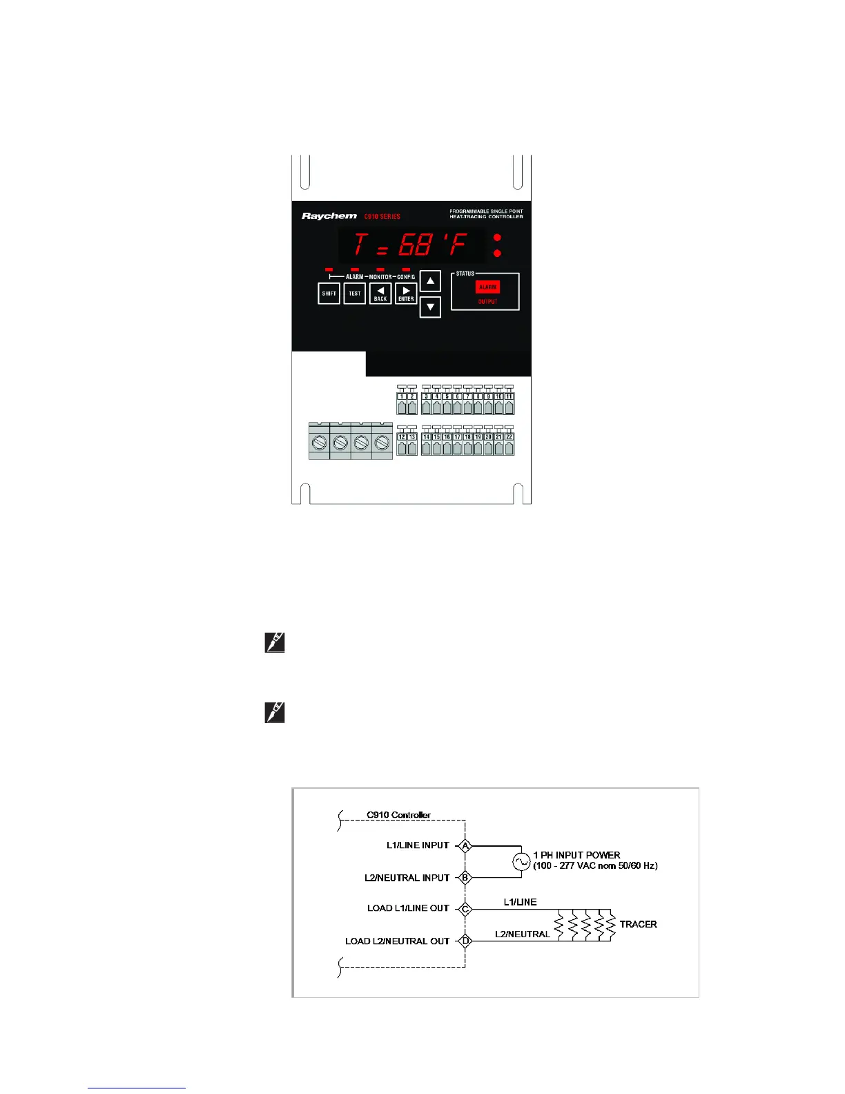
Figure 2.2 – Power Connection
2.5.1 Power Connections
The C910-485 controller may be powered directly from a 100 V to 277 V supply.
All of the power terminals are labeled for easy identification. Do not attempt to use wire
sizes that exceed the marked terminal ratings and avoid terminating two wires on the
same terminal whenever possible.
Note: Make sure that power terminals are retightened several days after installation.
Stranded wire will tend to compress when initially installed; therefore, these terminals
should be checked for tightness several times after the system is installed to ensure that
a good connection is maintained.
Note: Follow the industry standard grounding practices. Do not rely on conduit
connections to provide a suitable ground. Grounding terminals/screws are provided for
connection of system ground leads.
Figure 2.3 – Power Connection