Do you have a question about the Raychem C910-485 and is the answer not in the manual?
Manual provides installation, operation, testing, and maintenance info for the C910-485 Heat Trace Controller.
Controller monitors, communicates alarms/data for one heating cable circuit with RS-485 module.
Highlights alphanumeric display, temperature range, sensor inputs, and electromechanical relay output.
Details specifications including ground-fault, PASC, auto-cycling, sensor failure, communications, certification, and warranty.
Details relay type, voltage, current, control algorithms, control range, and temperature monitoring limits.
Covers programming methods, connection terminals, mounting, and communication protocol details.
Section covers initial inspection, preparation for use, and storage instructions for C910-485 controllers.
Instructions for inspecting shipping container and equipment for damage or defects upon arrival.
Guidance on selecting an installation location considering ambient temperature range and accessibility.
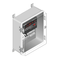
Details how to drill conduit entry holes and mount the enclosure using a template.
Describes forcing the controller on/off using an external device with a dry contact.
Details the two types of alarm relays (DC contact and AC relay) and their connection methods.
Illustrates wiring for the AC (triac) alarm relay as an AC alarm or powered AC alarm.
Describes the six-character, fourteen-segment LED display for messages and prompts.
Details the six keys for selecting console modes and their functions, including SHIFT key operations.
Default mode displaying load current, temperature, and setpoint readings sequentially.
Mode to examine or reset alarms, indicated by the ALARM key LED.
Mode to examine controller readings like temperature and load current, indicated by MONITOR key LED.
Mode to access console menus for examining or altering settings, indicated by CONFIG key LED.
Step-by-step guide on how to change display units between Imperial and Metric.
Step-by-step guide on how to change the switch control mode using the keypad.
Step-by-step guide on how to set or change the control setpoint temperature.
Step-by-step guide on how to set or change the deadband value.
Step-by-step guide on entering PASC setup parameters like pipe size, power adjust factor, and ambient temperature.
Step-by-step guide on how to enable or disable the low temperature sensor alarm.
Step-by-step guide on how to set the low temperature alarm setpoint for sensors 1 and 2.
Step-by-step guide on how to enable or disable the high temperature sensor alarm.
Step-by-step guide on how to set the high temperature alarm setpoint for sensors 1 and 2.
Step-by-step guide on how to enable or disable the temperature sensor failure alarm.
Step-by-step guide for selecting TS HI Limit enable/disable, setpoint, and alarm settings.
Step-by-step guide on how to enable or disable the low load current alarm.
Step-by-step guide on how to set the low load current alarm setpoint.
Step-by-step guide on how to load factory default settings.
Step-by-step guide on how to set the ground-fault current alarm level.
Step-by-step guide on how to set the ground-fault current trip level.
Step-by-step guide on configuring the temperature sensor failure mode to ON or OFF.
Step-by-step guide on changing the temperature sensor control mode.
Step-by-step guide on selecting Inhibit or Force ON mode using the external input.
Step-by-step guide on viewing the software version.
Step-by-step guide on entering or changing the controller's passcode.
Step-by-step guide on configuring communication parameters like protocol, address, baud rate, and parity.
Step-by-step guide on enabling or disabling the auto-cycle function.
Step-by-step guide on setting the auto-cycle interval.
Step-by-step guide on changing auto-cycle units between hours and minutes.
Step-by-step guide on changing the contactor count setting.
Step-by-step guide for entering the Monitor and Maintenance menus.
Table listing alarm types and their associated filter times.
Step-by-step guide on changing the alarm output state from N.C. to N.O.
Symptoms, causes (e.g., wrong RTD type), and corrective actions for RTD failure alarms.
Causes and corrective actions for inaccurate temperature readings, including wiring and RTD issues.
Covers causes like damaged extension wire or loose connections, and their corrective actions.
Addresses high temperature issues due to alarm settings or water flow, suggesting adjustments or checks.
Details issues related to the controlling sensor failure, including checking TS FAIL MODE and wiring.
Covers installation, wet components, or wiring leading to ground-fault alarms, recommending commissioning tests.
Addresses low current issues due to voltage problems or damaged heating cable, suggesting verification and replacement.
Explains how PASC utilizes ambient temperature to control heating cable power for energy efficiency.
| Power Supply | 24 VDC |
|---|---|
| Operating Temperature Range | -40°C to +70°C (-40°F to +158°F) |
| Storage Temperature Range | -40°C to +85°C (-40°F to +185°F) |
| Protection Features | Short circuit protection |
| Certifications | CE, UL |