Wuhan Raycus Fiber Laser Technologies Co., Ltd
User Guide
RFL-C2000S-HP /RFL-C3000S-HP /RFL-C4000S-HP/RFL-C6000S-HP
22
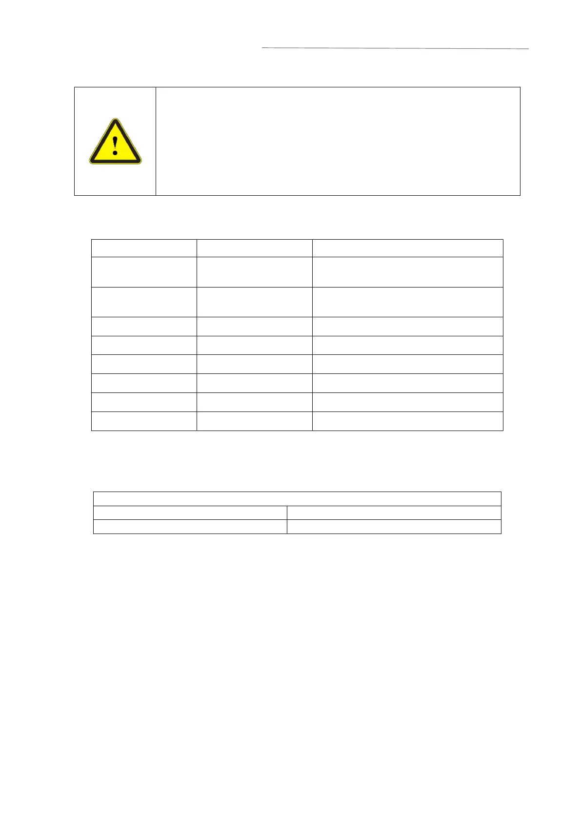
The Interlock interface shall not be connected to the active signal,
otherwise the interface will be damaged and the laser will alarm;
After all interlocks are closed, short circuit CTRL INTERFACEpin10
and 11for more than 0.5s, and power on the main power supply; If any
Interlock is disconnected, the main power supply will be turned off
immediately;
After the main power supply is disconnected, wait at least 10s before
re shorting CTRL INTERFACEpin 10 and 11.
4.4.2 Ethernet TCP/IP interface settings
Table 8 Definition of Ethernet interface pins
If conditions permit, please give priority to this interface to obtain better communication
stability. The laser and computer must be in the same LAN.
Table9 LaserIP address
IPconfiguration
:
a) Open“Local Area Connection”on your PC, and then click “Properties”;
b) Select“Internet Protocol Version 4”(TCP/IP 4);
c) Click
“
Properties
”
button
;
d) Select "Use the following IP address:" to manually assign IP addresses;
e) Assign an IP address of 192.168.0. x (x cannot be 10, because 192.168.0.10 has
been assigned to the laser), and then assign a subnetmask address, which is
255.255.255.0 by default;
f) Click
“
OK
”
to confirm the settings and exit. See Figure 7 for details.